LTM4664
Info : RECOMMENDED FOR NEW DESIGNS
searchIcon
cartIcon

LTM4664

54VIN Dual 25A, Single 50A µModule Regulator with Digital Power System Management

Show More showmore-icon

Info : RECOMMENDED FOR NEW DESIGNS tooltip
Part Models 2
1ku List Price Starting From $67.66
Features
  • Complete 48V Input to Low Voltage Dual 25A Supply that Can Scale to 300A
  • Dual Analog Loops with Digital Interface for Compensation, Control and Monitoring
  • Input Voltage Range: 30V to 58V
  • Output Voltage Range: 0.5V to 1.5V
  • ±3% Output Current Readback Accuracy (–20° to 125°C)
  • 88% Efficiency for 48V to 1V at 50A
  • ±0.5% Output Voltage Accuracy Over Temperature
  • 400kHz PMBus-Compliant I2C Serial Interface
  • 16mm × 16mm × 7.72mm BGA Package
Additional Details
show more Icon

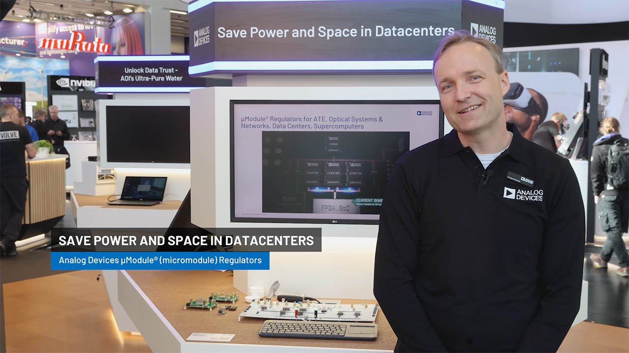
The LTM4664 is a complete non-isolated 48V input high efficiency step-down µModule® regulator with dual 25A outputs. The switching controllers, power MOSFETs, inductors and supporting components are included. Only external capacitors are needed to complete the design. Operating over a 30V to 58V input voltage range, the LTM4664 supports an output voltage of 0.5V to 1.5V at up to 75W. An intermediate output at 25% • VIN is also available. The LTM4664 product video is available on the website.

The LTM4664 dual 25A regulators utilize digitally programmable analog control loops, precision data acquisition circuitry and EEPROM with ECC. The LTM4664’s 2-wire serial interface allows the 25A outputs to be margined, tuned and ramped up and down at programmable slew rates and sequencing delay times. True input current sense, output currents and voltages, input and output power, temperatures, uptime and peak values are all readable. 

APPLICATIONS

  • 48V Systems
  • Computer and Networking Equipment
  • Electronic Test Equipment
  • Storage Systems
Part Models 2
1ku List Price Starting From $67.66

close icon

Documentation

Video

Part Model Pin/Package Drawing Documentation CAD Symbols, Footprints, and 3D Models
LTM4664EY#PBF
  • HTML
  • HTML
LTM4664IY#PBF
  • HTML
  • HTML

Filter by Model

reset

Reset Filters

Part Models

Product Lifecycle

PCN

Sep 13, 2022

- 22_0193

Laser Top Mark Conversion for uModule COP and TMSV_COP Packages

LTM4664EY#PBF

PRODUCTION

LTM4664IY#PBF

PRODUCTION

Feb 28, 2020

- 20_0123

Micro-Module, Test Site Transfer from Analog Devices Singapore to Analog Devices Penang, Malaysia

Feb 5, 2020

- 20_0127

Supplier Material Change for µModule

Filter by Model

reset

Reset Filters

Part Models

Product Lifecycle

PCN

Sep 13, 2022

- 22_0193

arrow down

Laser Top Mark Conversion for uModule COP and TMSV_COP Packages

LTM4664EY#PBF

PRODUCTION

LTM4664IY#PBF

PRODUCTION

Feb 28, 2020

- 20_0123

arrow down

Micro-Module, Test Site Transfer from Analog Devices Singapore to Analog Devices Penang, Malaysia

Feb 5, 2020

- 20_0127

arrow down

Supplier Material Change for µModule

Evaluation Kits 2

reference details image

DC2672A-A

LTM4664 Demo Board | 48VIN, Dual 25A μModule Regulator With Digital Power System Management

zoom

DC2672A-A

LTM4664 Demo Board | 48VIN, Dual 25A μModule Regulator With Digital Power System Management

LTM4664 Demo Board | 48VIN, Dual 25A μModule Regulator With Digital Power System Management

Product Detail

Demonstration circuit 2672A-A is a complete non-isolated 48V input, dual-output, high efficiency, high density µModule regulator with 30V to 58V input range. Each output can supply 25A maximum load current. The demo board has a LTM4664 µModule regulator, which is a dual 25A or single 50A step-down regulator with digital power system management. Please see the LTM4664 datasheet for more detailed information.

DC2672A-A powers up to default settings and produces power based on configuration resistors without the need for any serial bus communication. This allows easy evaluation of the DC/DC converter. To fully explore the extensive power system management features of the part, download the GUI software LTpowerPlay™ onto your PC and use ADI’s I2C/SMBus/PMBus dongle DC1613A to connect to the board. LTpowerPlay allows the user to reconfigure the part on the fly and store the configuration in EEPROM, view telemetry of voltage, current, temperature and fault status.

reference details image

DC2672A-B

LTM4664 Demo Board | 48VIN, Single 50A μModule Regulator With Digital Power System Management

zoom

DC2672A-B

LTM4664 Demo Board | 48VIN, Single 50A μModule Regulator With Digital Power System Management

LTM4664 Demo Board | 48VIN, Single 50A μModule Regulator With Digital Power System Management

Product Detail

Demonstration circuit 2672A-B is a complete non-isolated 48V input, dual-phase single output, high efficiency, high density µModule regulator with 30V to 58V input range. The output can supply 50A maximum load current. The demo board has a LTM4664 µModule regulator, which is a dual 25A or single 50A step-down regulator with digital power system management. Please see LTM4664 datasheet for more detailed information.

DC2672A-B powers up to default settings and produces power based on configuration resistors without the need for any serial bus communication. This allows easy evaluation of the DC/DC converter. To fully explore the extensive power system management features of the part, download the GUI software LTpowerPlay™ onto your PC and use ADI’s I2C/SMBus/PMBus dongle DC1613A to connect to the board. LTpowerPlay allows the user to reconfigure the part on the fly and store the configuration in EEPROM, view telemetry of voltage, current, temperature and fault status.

Tools & Simulations 1

LTspice® is a powerful, fast and free simulation software, schematic capture and waveform viewer with enhancements and models for improving the simulation of analog circuits.

To launch ready-to-run LTspice demonstration circuits for this part:

Step 1: Download and install LTspice on your computer.

Step 2: Click on the link in the section below to download a demonstration circuit.

Step 3: If LTspice does not automatically open after clicking the link below, you can instead run the simulation by right clicking on the link and selecting “Save Target As.” After saving the file to your computer, start LTspice and open the demonstration circuit by selecting ‘Open’ from the ‘File’ menu.

Recently Viewed