LTC4413
RECOMMENDED FOR NEW DESIGNSDual 2.6A, 2.5V to 5.5V, Ideal Diodes in 3mm × 3mm DFN
- Part Models
- 2
- 1ku List Price
- Starting From $3.70
Overview
- 2-Channel Ideal Diode ORing or Load Sharing
- Low Loss Replacement for ORing Diodes
- Low Forward On-Resistance (100mΩ Max at 3.6V)
- Low Reverse Leakage Current (1μA Max)
- Small Regulated Forward Voltage (28mV Typ)
- 2.5V to 5.5V Operating Range
- 2.6A Maximum Forward Current
- Internal Current Limit and Thermal Protection
- Slow Turn-On/Off to Protect Against Inductive Source Impedance-Induced Voltage Spiking
- Ultralow Quiescent Current Consumption, Low Power Alternative to the LTC4413-1
- Status Output to Indicate if Selected Channel is Conducting
- Programmable Channel On/Off
- Low Profile (0.75mm) 10-Lead 3mm × 3mm DFN Package
The LTC4413 contains two monolithic ideal diodes, each capable of supplying up to 2.6A from input voltages between 2.5V and 5.5V. Each ideal diode uses a 100mΩ P-channel MOSFET that independently connects INA to OUTA and INB to OUTB. During normal forward operation the voltage drop across each of these diodes is regulated to as low as 28mV. Quiescent current is less than 40μA for diode currents up to 1A. If either of the output voltages exceeds its respective input voltages, that MOSFET is turned off and less than 1μA of reverse current will flow from OUT to IN. Maximum forward current in each MOSFET is limited to a constant 2.6A and internal thermal limiting circuits protect the part during fault conditions.
Two active-high control pins independently turn off the two ideal diodes contained within the LTC4413, controlling the operation mode as described by Table 1. When the selected channel is reverse biased, or the LTC4413 is put into low power standby, a status signal indicates this condition with a low voltage.
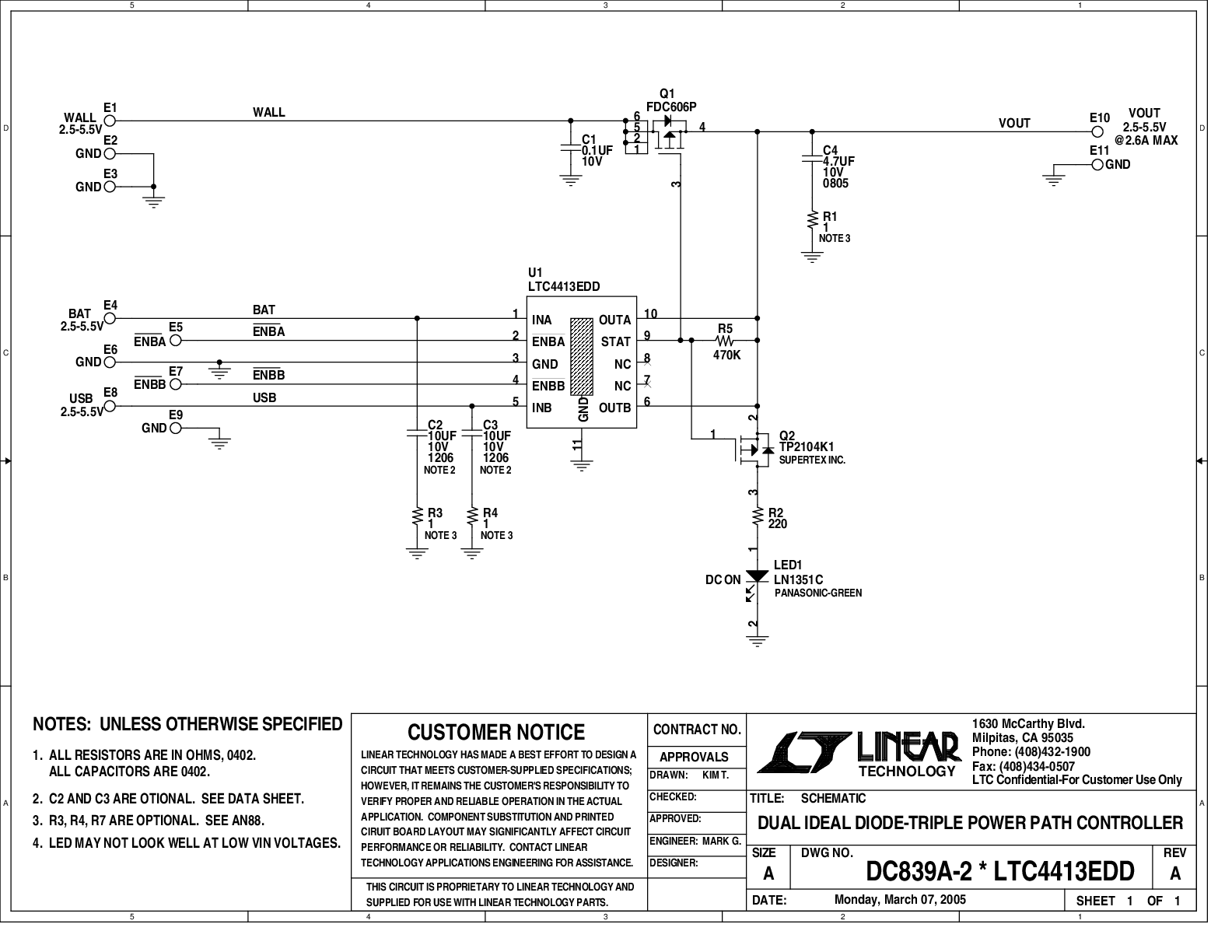
A 9μA open-drain STAT pin is used to indicate conduction status. When terminated to a positive supply through a 470k resistor, the STAT pin can be used to indicate that the selected diode is conducting with a high voltage. This signal can also be used to drive an auxiliary P-channel MOSFET power switch to control a third alternate power source when the LTC4413 is not conducting forward current.
The LTC4413 is housed in a 10-lead DFN package.
| Features | |
| LTC4413 | Lower Iq |
| LTC4413-1 | Lower Vfwd, Faster Response, Higher Iq |
| LTC4413-2 | Lower Vfwd, Faster Response, Higher Iq, 13V (max) OVP |
Applications
- Battery and Wall Adapter Diode ORing in Handheld Products
- Backup Battery Diode ORing
- Power Switching
- USB Peripherals
- Uninterruptable Supplies
Documentation
Data Sheet 1
User Guide 1
Design Note 2
Technical Articles 3
Press Release 1
Product Selection Guide 1
ADI has always placed the highest emphasis on delivering products that meet the maximum levels of quality and reliability. We achieve this by incorporating quality and reliability checks in every scope of product and process design, and in the manufacturing process as well. "Zero defects" for shipped products is always our goal. View our quality and reliability program and certifications for more information.
| Part Model | Pin/Package Drawing | Documentation | CAD Symbols, Footprints, and 3D Models |
|---|---|---|---|
| LTC4413EDD#PBF | 10-Lead DFN (3mm x 3mm w/ EP) | ||
| LTC4413EDD#TRPBF | 10-Lead DFN (3mm x 3mm w/ EP) |
This is the most up-to-date revision of the Data Sheet.
Software Resources
Can't find the software or driver you need?
Request a Driver/SoftwareHardware Ecosystem
| Parts | Product Life Cycle | Description |
|---|---|---|
| Hot Swap Controllers 1 | ||
|
LTC4361-1 LTC4361-2 |
Overvoltage/Overcurrent Protection Controller | |
Tools & Simulations
LTspice
Models for the following parts are available in LTspice:
- LTC4413
- LTC4413-1
- LTC4413-2
LTspice® is a powerful, fast and free simulation software, schematic capture and waveform viewer with enhancements and models for improving the simulation of analog circuits.