

ADP5041
PRODUCTIONMicro PMU with 1.2 A Buck, Two 300 mA LDOs, Supervisory, Watchdog, and Manual Reset
- Part Models
- 1
- 1ku List Price
- Starting From $2.91
Overview
- Input voltage range: 2.3 V to 5.5 V
- One 1.2 A buck regulator
- Two 300 mA LDOs
- 20-lead, 4 mm × 4 mm LFCSP package
- Overcurrent and thermal protection
- Soft start
- Undervoltage lockout
- Open-drain processor reset with externally adjustable threshold monitoring
- Guaranteed reset output valid to VAVIN = 1 V
- Manual reset input
- Watchdog refresh input
- Buck key specifications
- Output voltage range: 0.8 V to 3.8 V
- Current mode topology for excellent transient response
- 3 MHz operating frequency
- Peak efficiency up to 96%
- Uses tiny multilayer inductors and capacitors
- Mode pin selects forced PWM or auto PWM/PSM mode
- 100% duty cycle low dropout mode
- LDOs key specifications
- Output voltage range: 0.8 V to 5.2 V
- Low input supply voltage from 1.7 V to 5.5 V
- Stable with 2.2 μF ceramic output capacitors
- High PSRR
- Low output noise
- Low dropout voltage
- −40°C to +125°C junction temperature range
The ADP5041 combines one high performance buck regulator and two low dropout (LDO) regulators in a small 20-lead LFCSP to meet demanding performance and board space requirements.
The high switching frequency of the buck regulator enables use of tiny multilayer external components and minimizes board space.
When the MODE pin is set to logic high, the buck regulator operates in forced PWM mode. When the MODE pin is set to logic low, the buck regulator operates in PWM mode when the load is around the nominal value. When the load current falls below a predefined threshold, the regulator operates in power save mode (PSM), improving the light load efficiency. The low quiescent current, low dropout voltage, and wide input voltage range of the ADP5041 LDOs extend the battery life of portable devices. The ADP5041 LDOs maintain a power supply rejection greater than 60 dB for frequencies as high as 10 kHz while operating with a low headroom voltage.
Each regulator in the ADP5041 is activated by a high level on the respective enable pin. The output voltages of the regulators and the reset threshold are programmed through external resistor dividers to address a variety of applications. The ADP5041 contains supervisory circuits that monitor power supply voltage levels and code execution integrity in microprocessor-based systems. They also provide power-on reset signals. An on-chip watchdog timer can reset the microprocessor if it fails to strobe within a preset timeout period.
Documentation
Data Sheet 1
User Guide 1
Brochure 1
ADI has always placed the highest emphasis on delivering products that meet the maximum levels of quality and reliability. We achieve this by incorporating quality and reliability checks in every scope of product and process design, and in the manufacturing process as well. "Zero defects" for shipped products is always our goal. View our quality and reliability program and certifications for more information.
| Part Model | Pin/Package Drawing | Documentation | CAD Symbols, Footprints, and 3D Models |
|---|---|---|---|
| ADP5041ACPZ-1-R7 | 20-Lead LFCSP (4mm x 4mm w/ EP) |
| Part Models | Product Lifecycle | PCN |
|---|---|---|
|
Feb 6, 2017 - 16_0234 Assembly Transfer to ASE Korea and Test Transfer to STATS ChipPAC Singapore of Select LFCSP Parts. |
||
| ADP5041ACPZ-1-R7 | PRODUCTION | |
|
Aug 6, 2014 - 13_0230 Assembly and Test Transfer of Select 3.5x3.5, 4x3, 4x4, and 5x5mm LFCSP Products to STATS ChipPAC China |
||
| ADP5041ACPZ-1-R7 | PRODUCTION | |
This is the most up-to-date revision of the Data Sheet.
Software Resources
Can't find the software or driver you need?
Request a Driver/SoftwareTools & Simulations
5V uPMU BuckDesigner
Microsoft Excel download tool from ADIsimPower to generate a power supply design complete with a schematic, bill of materials, and performance specifications.
Open ToolEvaluation Kits
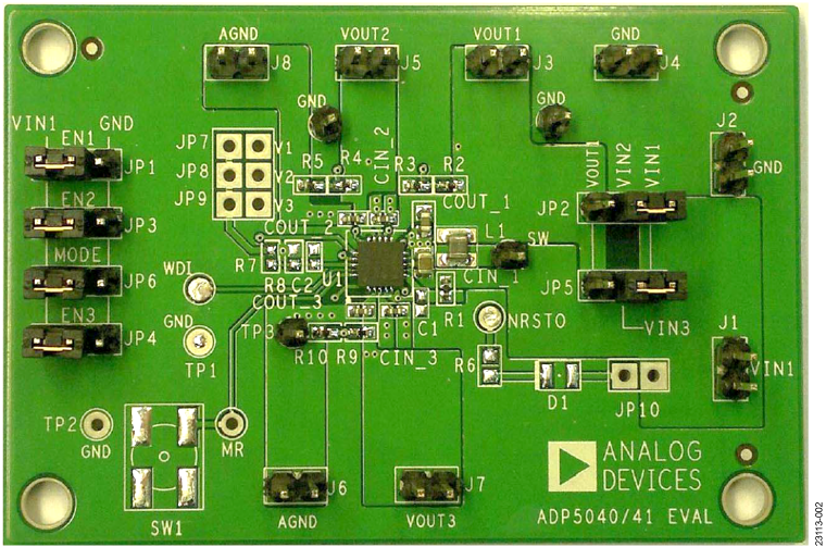
Evaluating the ADP5041 Micropower Management Units (PMUs)
Resources
Evaluating the ADP5041 Micropower Management Units (PMUs)
Resources
Latest Discussions
No discussions on ADP5041 yet. Have something to say?
Start a Discussion on EngineerZone®