ADM1272
warning : LAST TIME BUY
searchIcon
cartIcon

ADM1272

High Voltage Positive Hot Swap Controller and Digital Power Monitor with PMBus

Show More showmore-icon

warning : LAST TIME BUY tooltip
Part Models 2
1ku List Price Starting From $11.99
Features
  • Controls supply voltages from 16 V to 80 V (absolute maximum 120 V)
  • High voltage (80 V) IPC-9592 compliant packaging
  • <500 ns response time to short circuit
  • FET energy monitoring for adaptable FET SOA protection
  • Gate boost mode for fast recovery from OC transients
  • Programmable random start mode to stagger power-on
  • FET fault detection
  • Remote temperature sensing with programmable warning and shutdown thresholds
  • Programmable 2.5 mV to 30 mV system current-limit setting range
  • ±0.85% accurate current measurement with 12-bit ADC
  • ILOAD, VIN, VOUT, temperature, power, and energy telemetry
  • Programmable start-up current limit
  • Programmable linear output voltage soft start
  • 1% accurate UV and OV thresholds
  • Programmable hot swap restart function
  • 2 programmable GPIO pins
  • Reports power and energy consumption
  • Peak detect registers for current, voltage, and power
  • PMBus fast mode compliant interface
  • 48-lead 7 mm × 8 mm LFCSP
Additional Details
show more Icon

The ADM1272  is a hot swap controller that allows a circuit board to be removed from or inserted into a live backplane. It also features current, voltage, and power readback via an integrated 12-bit analog-to-digital converter (ADC), accessed using a PMBus interface. This device is able to withstand up to 120 V, which makes it very robust in surviving surges and transients commonly associated with high voltage systems, usually clamped using protection devices such as transient voltage suppressors (TVSs) that can often exceed 100 V.

The load current, ILOAD, is measured using an internal current sense amplifier that measures the voltage across a sense resistor in the power path via the SENSE+ and SENSE− pins. A default current limit sense voltage of 30 mV is set, but this limit can be adjusted down, if required, using a resistor divider network from the VCAP regulator output voltage to the ISET pin. An additional resistor can also be placed from ISET to VIN (or VOUT) to allow the current limit to track inversely with the rail voltage. This resistor allows an approximate system power limit to be used.

The ADM1272  limits the current through the sense resistor by controlling the gate voltage of an external N channel field effect transistor (FET) in the power path. The sense voltage, and therefore the load current, is maintained below the preset maximum. The ADM1272  protects the external FET by monitoring and limiting the energy transfer through the FET while the current is being controlled. This energy limit is set by the choice of components connected to the EFAULT pin (for fault protection mode) and the ESTART pin during startup. Therefore, different energy limits can be set for start-up and normal fault conditions. During startup, inrush currents are maintained very low and different areas of the safe operating area (SOA) curve are of interest, whereas during fault conditions, the currents can be much higher.

The controller uses the drain to source voltage (VDS) across the FET to set the current profile of the EFAULT and ESTART pins and, therefore, the amount of much energy allowed to be transferred in the FET. This energy limit ensures the MOSFET remains within the SOA limits. Optionally, use a capacitor on the DVDT pin to set the output voltage ramp rate, if required. In case of a short-circuit event, a fast internal overcurrent detector responds in hundreds of ns and signals the gate to shut down. A 1.5 A pull-down device ensures a fast FET response. The gate then recovers control within 50 µs to ensure minimal disruption during conditions, such as line steps and surges. The ADM1272  features overvoltage (OV) and undervoltage (UV) protection, programmed using external resistor dividers on the UVH, UVL, and OV pins. The use of two pins for undervoltage allows independent accurate rising and falling thresholds. The PWRGD output pin signals when the output voltage is valid and the gate is sufficiently enhanced. The validity of VOUT is determined using the PWGIN pin.

The 12-bit ADC measures the voltage across the sense resistor, the supply voltage on the SENSE+ pin, the output voltage, and the temperature using an external NPN/PNP device. A PMBus interface allows a controller to read data from the ADC. As many as 16 unique I2C addresses can be selected, depending on how the two ADRx pins are connected. The ADM1272 is available in a custom 48-lead LFCSP (7 mm × 8 mm) with a pinstrap mode that allows the device to be configured for automatic retry or latchoff when an overcurrent (OC) fault occurs.

Applications

  • 48 V/54 V systems
  • Servers
  • Power monitoring and control/power budgeting
  • Central office equipment
  • Telecommunication and data communication equipment
  • Industrial applications
Part Models 2
1ku List Price Starting From $11.99

close icon

Documentation

Video

Part Model Pin/Package Drawing Documentation CAD Symbols, Footprints, and 3D Models
ADM1272-1ACPZ
  • HTML
  • HTML
ADM1272-1ACPZ-RL
  • HTML
  • HTML

Filter by Model

reset

Reset Filters

Part Models

Product Lifecycle

PCN

Oct 1, 2024

- 24_0070

Obsolescence of ADM1075 and ADM1272

ADM1272-1ACPZ

LAST TIME BUY

ADM1272-1ACPZ-RL

LAST TIME BUY

Filter by Model

reset

Reset Filters

Part Models

Product Lifecycle

PCN

Oct 1, 2024

- 24_0070

arrow down

Obsolescence of ADM1075 and ADM1272

ADM1272-1ACPZ

LAST TIME BUY

ADM1272-1ACPZ-RL

LAST TIME BUY

Evaluation Kits 1

reference details image

EVAL-ADM1272

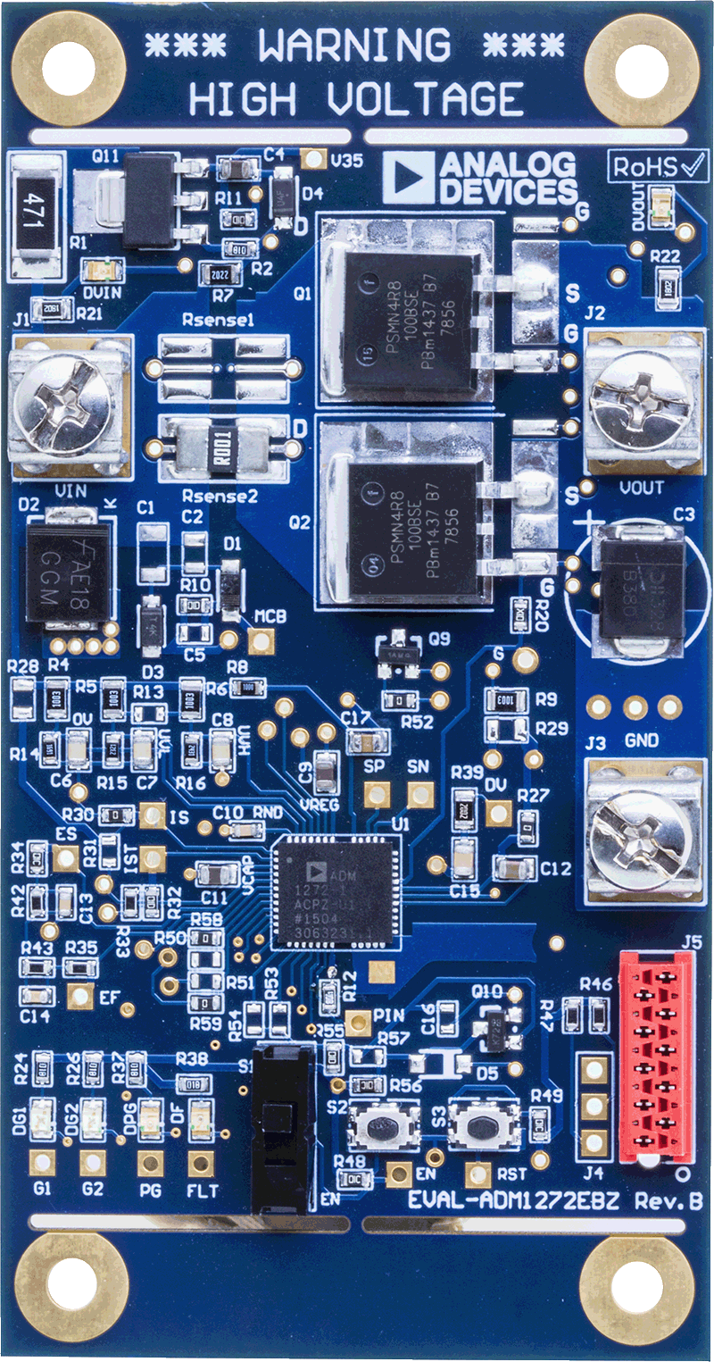
ADM1272 Evaluation Board

zoom

EVAL-ADM1272

ADM1272 Evaluation Board

ADM1272 Evaluation Board

Features and Benefits

  • Fully functional support evaluation kit for the ADM1272
  • Populated and tested with 48 V, 30 A, 1 mF design
  • 40 V undervoltage and 60 V overvoltage settings
  • Custom N-MOSFET footprint suits different packages
  • Supports up to 2 sense resistors in parallel
  • Supports up to 4 FETs in parallel
  • LED indicated status outputs
  • Wide input voltage range 16 V to 80 V
  • 120 V absolute maximum
  • FET temperature measurement capability
  • Supports cascade setup for multiple boards
  • Toggle and push-button switch for easy input control
  • PMBus (I2C) communication supported

Product Detail

The EVAL-ADM1272EBZ is a compact, full featured evaluation board for the ADM1272. The board layout provides a clear visual of all the peripheral components and the hot swap power path. The layout also maximizes the ability of the board to dissipate heat for some of the key components on the power path, allowing the evaluation of high current hot swap setups.


Two sense-resistor slots and four (two on the bottom side) multipackage FET slots provide great flexibility and allow a wide range of application setups.


Multiple test points allow easy access to all critical points and pins. Six LEDs provide direct visual indication on variations in the board status, such as supply input, output, GPIO1, GPIO2, power good, and fault.


The kit supports PMBus communication, allowing users to communicate with the ADM1272. The evaluation kit also supports cascade setup so that multiple evaluation boards can be connected together and share the same PMBus.


The boards are fully compatible with the ADM1272 evaluation software, which can be downloaded from the ADM1272 product page.


A USB-to-I2C dongle (USB-SDP-CABLEZ) is required to use the evaluation software.


The standard evaluation kit is prepopulated and tested with a 48 V, 30 A hot swap design capable of working with a 1 mF output capacitor.


Complete specifications for the ADM1272 are available in the ADM1272 data sheet, which must be consulted in conjunction with user guide (UG-990) when using the evaluation board.

Tools & Simulations 2

LTspice® is a powerful, fast and free simulation software, schematic capture and waveform viewer with enhancements and models for improving the simulation of analog circuits.

To launch ready-to-run LTspice demonstration circuits for this part:

Step 1: Download and install LTspice on your computer.

Step 2: Click on the link in the section below to download a demonstration circuit.

Step 3: If LTspice does not automatically open after clicking the link below, you can instead run the simulation by right clicking on the link and selecting “Save Target As.” After saving the file to your computer, start LTspice and open the demonstration circuit by selecting ‘Open’ from the ‘File’ menu.

Recently Viewed