ADG1534
RECOMMENDED FOR NEW DESIGNS4.5 Ω RON, 1.8 V Logic-Compatible Quad SPDT Switch
- Part Models
- 1
- 1ku List Price
- Starting From $3.19
Overview
- 4.5 Ω typical on resistance for +5 V to −8 V supply at 25°C
- 1.2 Ω on-resistance flatness for +5 V to −8 V supply at 25°C
- Up to 346 mA continuous current
- Fully specified
- VDD = +5 V ± 10%
- VSS = −4.5 V to −8.8 V
- No VL supply required
- 1.8 V logic-compatible inputs
- Rail-to-rail operation
- 20-lead, 4 mm × 4 mm LFCSP
The ADG1534 contains four independent SPDT switches. An EN input on the ADG1534 is used to enable or disable the device. When disabled, all channels are high impedance. The digital inputs, INx, are 1.8 V logic-compatible and suitable for low voltage logic controls.
The ADG1534 is fully specified at VDD = +5 V ± 10% and VSS = −4.5 V to −8.8 V for applications that require asymmetrical supplies. The ultra-low on resistance and on-resistance flatness of the switches makes it an ideal solution for data acquisition and gain switching applications, where low distortion is critical. The construction ensures ultra-low power dissipation, making the device ideally-suited for portable and battery-powered instruments.
The switch conducts equally well in both directions when on and has an input signal range that extends to the supplies. In the off condition, signal levels up to the supplies are blocked. All channels exhibit a break-before-make switching action that prevents momentary shorting when switching channels.
PRODUCT HIGHLIGHTS
- 8 Ω maximum on resistance over temperature.
- Minimum distortion.
- 1.8 V logic-compatible digital inputs.
- No logic power supply (VL) required.
- 20-lead, 4 mm × 4 mm LFCSP.
APPLICATIONS
- LDMOS power amplifier gate drive
- GaN power amplifier gate drive
- Communication systems
- Automatic test equipment
- Data acquisition systems
- Sample-and-hold systems
Documentation
Data Sheet 1
User Guide 1
ADI has always placed the highest emphasis on delivering products that meet the maximum levels of quality and reliability. We achieve this by incorporating quality and reliability checks in every scope of product and process design, and in the manufacturing process as well. "Zero defects" for shipped products is always our goal. View our quality and reliability program and certifications for more information.
| Part Model | Pin/Package Drawing | Documentation | CAD Symbols, Footprints, and 3D Models |
|---|---|---|---|
| ADG1534BCPZ-REEL7 | 20-Lead LFCSP (4mm x 4mm w/ EP) |
This is the most up-to-date revision of the Data Sheet.
Software Resources
Can't find the software or driver you need?
Request a Driver/SoftwareTools & Simulations
LTspice
Models for the following parts are available in LTspice:
- ADG1534
IBIS Model 1
LTspice® is a powerful, fast and free simulation software, schematic capture and waveform viewer with enhancements and models for improving the simulation of analog circuits.
Evaluation Kits
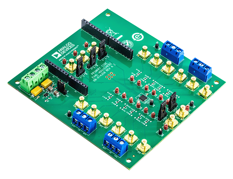
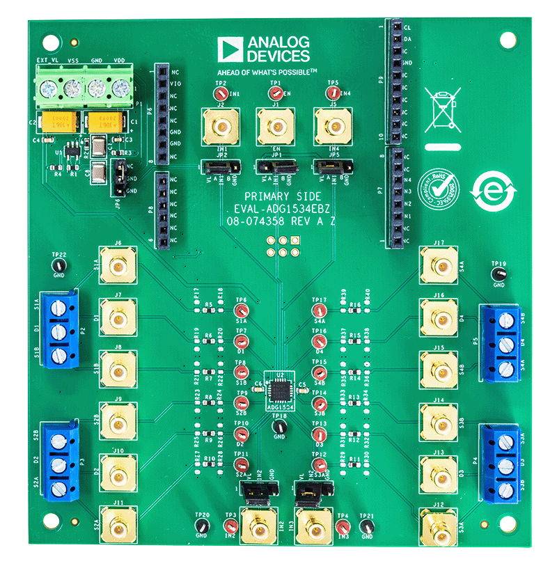

Evaluating the ADG1534 4.5 Ω RON, 1.8 V Logic-Compatible, Quad SPDT Switch
Resources
Latest Discussions
No discussions on ADG1534 yet. Have something to say?
Start a Discussion on EngineerZone®