The Low Output Voltage Ripple Zeta DC/DC Converter Topology
In the world of switching DC/DC converters the Zeta topology is a lesser known relative of the SEPIC topology. Both converters provide a positive output voltage that can be greater than, equal to or less than VIN while avoiding the complexity and cost of a buck-boost converter. The Zeta converter however, has the advantage of significantly reduced output ripple voltage.
Zeta and SEPIC Similarities
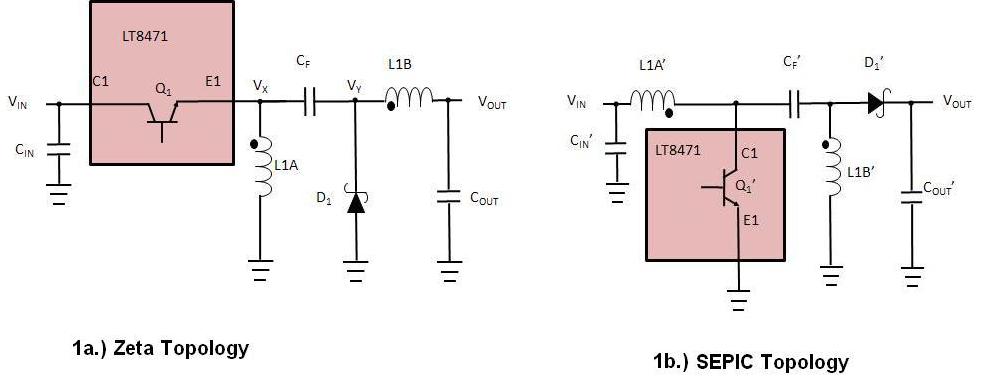
To compare topologies, we use the LT8471 Dual Multitopology DC/DC Converter which features two 2A/50V power switches and antiphase switching for reduced input and output ripple. The SEPIC topology is popular because it is easily implemented with many boost converter ICs (including the LT8471) and it has continuous input current, which is often desired in battery-powered systems to minimize large pulse current drain from the battery. The Zeta, with its reduced VOUT ripple, is not compatible with most switching regulator ICs due to the negative voltages required on the VX node (Figure 1).
Figures 1a and 1b are simplified schematics of the Zeta and SEPIC topologies using the LT8471. Each topology requires two inductors (L1A & L1B), two switches (Q1 & D1), and a flying capacitor (CF). The Zeta rearranges the SEPIC's components such that an inductor is in series with VOUT (which we will see significantly reducing VOUT ripple). Note that L1A & L1B can be, and often are, 1:1 coupled inductors in a single package to minimize board space.
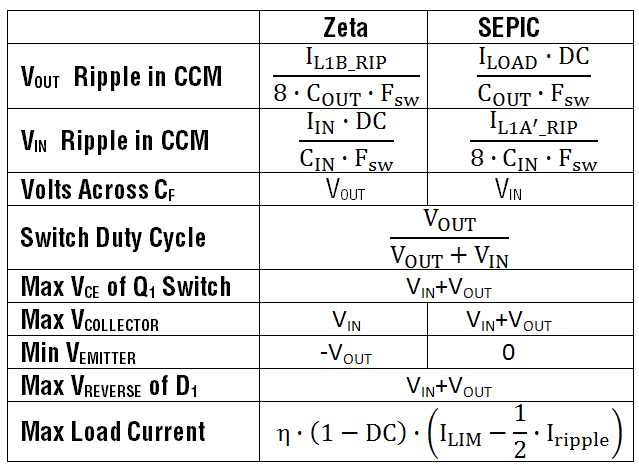
The Zeta and SEPIC converters use the same equation for calculating the switch duty cycle in continuous conduction mode, and given that they have the same switch current limit and combined inductor current ripple (for the two inductors), they both deliver the same maximum current to the load, which is:

where ILIM is the Q1 switch current limit, DC is the duty cycle, IL1_RIP is the combined inductor current ripple and η is the conversion efficiency (typically about 80% for the Zeta and SEPIC). Additionally, the diode and power switch requirements, VREVERSE and VCE respectively (see Table 1), are the same for the Zeta and the SEPIC converter.
Zeta and SEPIC Differences
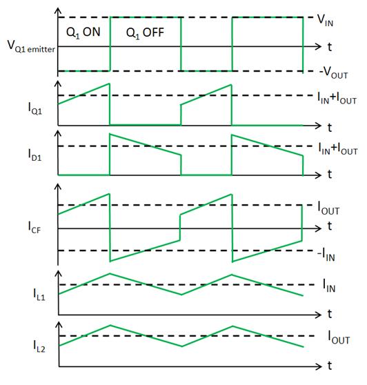
With a SEPIC converter (Figure 1b), the lowside Q1' switch periodically pulls VX' to ground, ramping up the inductor current. Q1' then turns off, after which VX' flies up to VOUT+VIN, delivering current through D1' to the output. With the Zeta converter (Figure 1a), the Q1 switch first pulls VX up to VIN then turns off, after which VX flies down to -VOUT. The LT8471 has a unique and flexible NPN power switch design capable of handling ‑60V on the emitter, allowing it to be used with the Zeta along with other, more familiar (Boost, Buck, SEPIC, etc.), topologies.In Figures 1a and 1b, both topologies use the same number of passive components. Note however, that the SEPIC uses a lowside power switch Q1' similar to that used in a boost converter, while the Zeta requires a highside switch Q1. Figure 2 shows the Zeta converter current flow and switching waveforms. The Q1 emitter voltage toggles between VIN and -VOUT. Therefore, the E1 pin must be rated to swing to -VOUT.
Output Voltage Ripple
Similar to the buck and Ćuk converters, the Zeta has very low output voltage ripple. Each of these converters has an inductor in series with VOUT preventing rapid changes in output current that would otherwise increase ripple voltage. Neglecting the ESR of COUT, VOUT ripple of the Zeta operating in CCM is given by:

where IL1B_RIP is the peak-to-peak ripple of the L1B inductor current and FSW is the switching frequency of the converter.
With the SEPIC, current out of the device only flows through D1' when Q1' is off. This makes the output current discontinuous and increases voltage ripple. Neglecting the ESR of COUT, VOUT ripple of the SEPIC operating in CCM is given by:

where ILOAD is the output load current and DC is the switching duty cycle.
From the equations above, and considering that IL1B_RIP is typically a fraction of ILOAD, it can be seen that the Zeta converter will have much lower VOUT ripple than the SEPIC converter.
Input Voltage Ripple
Neglecting the ESR of CIN, VIN ripple of the Zeta operating in CCM is given by:

the SEPIC converter input voltage ripple in CCM is given by:

where CIN is the input capacitor, IL1A'_RIP is the input inductor's current ripple.
Therefore, in contrast to the output voltage ripple, the Zeta converter will often have higher input voltage ripple than the SEPIC converter.
Component Voltage Ratings
Table 1 compares the Zeta and SEPIC converters. It lists the voltage ratings required for the power switch (Q1), power diode (D1) and the flying capacitor (CF). Note that the flying capacitor and power switch terminal voltages (Emitter and Collector) differ depending on the topology.
Low VOUT Ripple Application
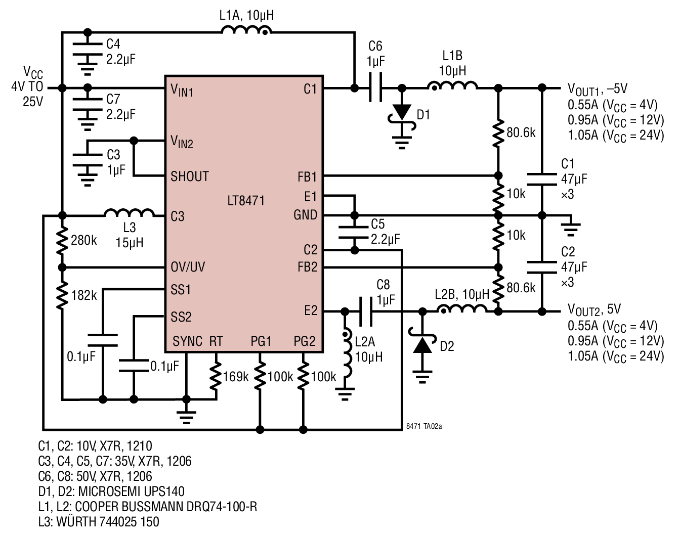
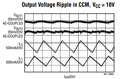
Figure 3 shows an example application using the LT8471 Dual Multitopology DC/DC Converter with 2A switches. This application creates +/- 5V output rails, both using low ripple topologies. Channel 1 creates the -5V output using the low output ripple ĆUK topology. Channel 2 creates the +5V output using the low output ripple Zeta topology. The input voltage can vary from 4V to 25V.
Using this configuration, both outputs have very low voltage ripple, which is less than 10mV, as shown in Figure 4.
Conclusion
When a low ripple, positive output voltage is required, consider choosing the Zeta topology. Similar to the SEPIC, it generates a regulated output voltage from an input voltage that can be greater than, equal to or less than the output voltage. Due to its unique NPN power switch design, the LT8471 DC/DC converter is nicely suited for creating Zeta DC/DC converters.


