Simplify AISG Control Systems by Integrating the Hardware Discrete Transceiver
摘要
This article describes the Antenna Interface Standards Group (AISG) standard in telecommunications and details its hardware implementation. It explains how a fully integrated transceiver such as the MAX9947 can help reduce space and cost, and solve bus arbitrations in base-station tower equipment.
A similar version of this article appeared in ECN on January 18, 2012.
Introduction
The latest generations of wireless networks have been developed to provide the high-speed data services required by data-intensive smartphone applications. Yet, deployment of this infrastructure has been costly, and coverage has been notably inadequate in some areas.
Addressing both of these concerns, the Antenna Interface Standards Group (AISG) developed an open interface protocol to enable intelligent antenna systems. The AISG specification allows digital remote control and monitoring of wireless infrastructure to dynamically optimize the network based on changing coverage requirements. In particular, the protocol allows the implementation of a remote electric tilt (RET) device for the antenna.
This open standard has quickly been adopted by telecommunications companies because it frees them from proprietary solutions, while protecting their infrastructural investments. In turn, base-station and antenna manufacturers have benefited from a standardized technology roadmap, which has increased efficiency in product planning.
Base-Station Systems and AISG
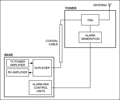
In a typical base-station system, such as the one illustrated in Figure 1, a coaxial cable allows the RF data communication between equipment that is placed at the top of the antenna's tower and the controlling equipment that sits at its base. A tower-mounted amplifier (TMA) is a low-noise preamplifier that is placed at the tower, right after the antenna, on the RF data receiving path. Its main function is to increase the signal-to-noise ratio (SNR) of the received signal. The equipment at the base consists of a duplexer filter that separates the two different frequencies of the transmitting and receiving paths, a transmission power amplifier, and a receiver amplifier. To monitor the proper functionality of the tower equipment, an alarm system is implemented and a separate cable is used to transmit alarm messages from the tower to the controlling equipment at the base.

Figure 1. Base-station system architecture prior to AISG.
After 2004, the wireless network 3G standard stipulated that the antenna's tilt must be controlled and its position adjusted dynamically to optimize the radiated signal. A proper device for that adjustment is a RET and has been added to the tower equipment. The AISG standard protocol was born soon thereafter with the main purpose of driving the RET device remotely from the base with a standardized communication protocol.
The system of Figure 2 illustrates the implementation of a base-station system that complies with the AISG standard protocol. The protocol was also adopted to carry the alarm information. Because of the low-frequency modulation of the AISG data, it is now also possible to use the same coaxial cable both to transmit RF data and handle the AISG signaling. This multiple functionality reduces the cabling requirements. Furthermore, with the use of devices called "bias-T" it is also possible to carry the supply voltage (typically 30V) from the base to the tower equipment in the same coaxial cable.

Figure 2. Base-station system architecture with AISG.
Basics of an AISG Application
AISG defines a protocol for communication between the base station and the tower equipment that uses a 2.176MHz sine-wave carrier with on-off-key (OOK) modulation. The communication is bidirectional, half-duplex, with a master (the base station) and a slave (the tower). The communication remotely changes the tilt of the antenna (RET) with commands from the base station. Also it monitors the status of the equipment in the tower, such as the RET and TMA.
AISG transceivers can be implemented discretely using any number of components and methods. They might use active or passive filters, different methods for OOK modulation and demodulation, and logic for bus arbitration and amplifiers. For each design there was a different method for achieving the standard; any product brought to market needed to create a transparent solution for AISG implementation.
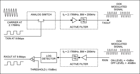
Figure 3 illustrates a possible discrete implementation of such a transceiver. A simple OOK modulator can be implemented with an analog switch. However, the very stringent AISG spectrum-emission profile requirements put considerable burden on the bandpass filter design, requiring fifth- or sixth-order implementation. The receiver uses the same selective filter, a peak demodulator, and a digital data's reconstructing comparator.

Figure 3. Discrete implementation of the AISG transceiver.
The First Fully Integrated Transceiver
The component count needed to implement the AISG communications can be reduced further by integrating the key functions. The MAX9947 does just that—it is the only single-chip AISG-compliant transceiver currently available. Integrated on the chip are the transmitter, receiver, and active filters. This solution reduces the hassle and expense of working with discrete solutions and drastically reduces the time needed to implement the AISG protocol.
The MAX9947's transmitter includes an OOK modulator; a bandpass filter that is compliant with the AISG spectrum-emission profile and operates around 2.176MHz; and an output amplifier with configurable output level. The receiver includes a bandpass filter that operates around the 2.176MHz center frequency with a narrow 200kHz bandwidth; it also includes an OOK demodulator and a comparator that reconstruct the digital signal. The device supports all the three data rates of the AISG standard: 9.6kbps, 38.4kbps, and 115.2kbps.
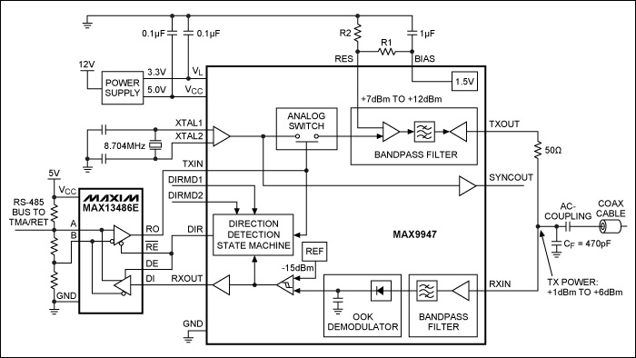
Figures 4 and 5 show the functionality of the MAX9947 as well as the system-level implementation of the AISG at the base station (Figure 4) and at the tower (Figure 5). An OOK modulated signal at TXOUT and the reconstructed digital signal at RXOUT are shown in Figures 6 and 7, respectively.

Figure 4. Implementation of the AISG functionality at the base station. The FPGA transmits and receives digital data to and from the MAX9947, which modulates and demodulates the OOK signal at the coaxial cable.

Figure 5. Implementation of the AISG functionality at the tower. The AISG transceiver interfaces between the OOK signal at the cable and the RS-485 digital signal at the left side of the MAX13486E RS-485 interface transceiver. The MAX9947's direction output (DIR) drives the direction of the data within the RS-485 transceiver.

Figure 6. The MAX9947 modulates the digital data at its TXIN input and generates the OOK signal (at TXOUT). The data rate is 9.6kbps.

Figure 7. The MAX9947 demodulates the OOK signal at its RXIN input and reconstructs the digital data at RXOUT. The data rate is 9.6kbps.
Autodirection Output
There can be multiple antennas in the tower, with multiple RETs and TMAs. All this equipment communicates in a daisy-chain fashion through the RS-485 bus. The MAX9947 (used to modulate and demodulate the OOK signal through the coaxial cable) interfaces with the RS-485 bus through a RS-485 transceiver, such as for example, the MAX13486E (Figure 5).
The MAX9947 provides an autodirection output (DIR) to facilitate RS-485 bus arbitration in the tower equipment (slave) without involving the microcontroller. The base station (master) determines the direction of the data flow, while the tower equipment (slave) decodes the information and responds to commands from the master. The transceiver chip's direction output removes the burden of the RS-485 bus arbitration from the slave microcontroller.
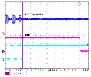
When data are coming from the base station and are being demodulated at RXOUT, the direction output, DIR, on the transceiver chip is set to high to put the MAX13486E into driving mode to drive the RS-485 bus. DIR is released within 16 bit-times after the last stop bit. This interval is in compliance with the AISG protocol, which requests that the bus be released within 20 bit-times (Figure 8).

Figure 8. The direction output (DIR) of the MAX9947 is released within 16 bit-times from the last bit of demodulated RXOUT data. The data rate is 115.2kbps.
The default condition is when data are coming from the RS-485 bus to the TXIN input of the transceiver, the MAX9947. In this case the output DIR is low and the bus interface chip, the MAX13486E, is in its receiving mode.
The transceiver chip's direction output eliminates the need to drive the interface chip's enable pins from the microcontroller.
Conclusion
AISG has addressed the need among telecommunication vendors for a standard protocol for communication between base station and tower equipment. Integrated AISG transceiver chips such as the MAX9947 provide a fully integrated solution to modulate and demodulate the OOK signal used in the protocol. These single-chip solutions save design space and cost, and simplify the arbitration of the data flow in the tower equipment.


