Protect Your Integrated-FET Power Switches with Automatic Current-Limit Adjustment
摘要
Some types of loads require more current during startup than when running. Other loads can be limited to a lower-power current during startup but require a higher operating current. This article describes an application circuit that automatically adjusts a power circuit's overcurrent protection level up or down after startup is complete.
Introduction
Placing a switch and a fuse between a power supply and its load allows for control and protection of power. An improvement on a simple switch and fuse is an integrated circuit that accomplishes the same functions in a single package with no moving parts and no need for service. This article will show how an internal power MOSFET and a driver circuit in the MAX5976 hot-swap power solution can provide on-off control and protection. The desired overcurrent protection level is set by a single external resistor to ground.
While specific functional details and features vary, most integrated load switches use a basic set of operating principles. During startup, the driver circuit in the load switch turns on its MOSFET while monitoring the load current and the temperature of the MOSFET switch. If the startup current reaches the programmed overcurrent limit before the MOSFET is fully on, the driver circuit briefly reduces the gate drive so that the load switch device acts like a constant current source. This mode of operation can continue for a limited time. If the output has not risen close to the input voltage at the end of this interval, the load switch will shut down and assert a fault-status output to indicate the failed startup. If the output successfully rises before the startup timer elapses, a power-good status output is asserted.
If the load current rises above the programmed overcurrent limit any time after startup, the load switch will function as an electronic circuit-breaker and shut down the internal power switch. This protects the upstream supply against the output-overload or short-circuit condition.
Changing the Overcurrent Threshold After Startup
Some load devices require more current during startup than when they are running. For example, loads with large input bypass capacitance may require a large charging current, but consume very little operating current once powered up. Similarly, devices with motors (such as a disk drive) can require large spin-up current, but once up to speed, the motor may draw much less.
To provide the best protection in these cases, it is advantageous to set the overcurrent protection threshold close to the lower running current. This can, however, result in a current-starved situation during startup when a load switch, such as the MAX5976, clamps the current and the output voltage fails to rise. In fact, output voltage may even fold back under this condition.
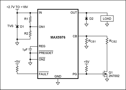
To solve this problem, a simple inverting scheme employs the load switch's open-drain power-good output (PG) to connect a second current-limit configuration resistance in parallel after startup. This design (Figure 1) reduces the current available to the load after startup is complete. During startup, while the output voltage is below the input, the PG output pulls low and the current limit is set by RCB1. After the output rises and the 16ms power-good delay elapses, the PG output goes high impedance. This allows the gate of Q1 to rise, connecting the second resistor, RCB2, in parallel with RCB1 and reducing the overcurrent threshold.

Figure 1. PG output controls an external transistor to reduce the overcurrent limit after startup.
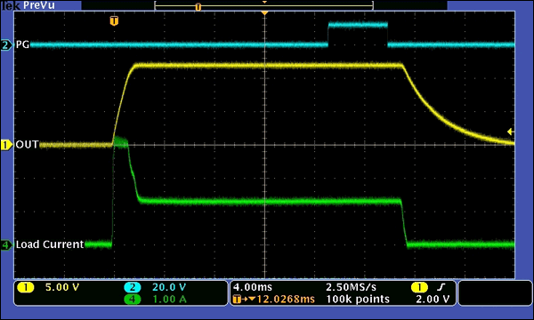
The operation of this circuit is shown in Figure 2, where the MAX5976 starts up into a 330µF, 8.9Ω load. Initially, the MAX5976 clamps the inrush current to 3A, set by RCB1 = 17.4kΩ. After VOUT comes up, the current through the load resistance is 1.3A. The PG output goes high 16ms after VOUT rises, thereby connecting RCB2 = 12.1kΩ in parallel with RCB1 and reducing the circuit-breaker limit to 1.25A. The MAX5976 circuit-breaker comparator tolerates this slight overcurrent condition for an additional 4.8ms and then shuts down. (If the overload is greater, the circuit-breaker comparator trips more quickly.)
 CB1 = 17.4kΩ and RCB2 = 12.1kΩ.">
Figure 2. Circuit of Figure 1 starting up into a 330µF, 8.9Ω load with RCB1 = 17.4kΩ and RCB2 = 12.1kΩ.
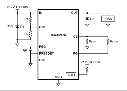
Conversely, some loads must be started slowly to avoid excessive power dissipation in the load switch's internal MOSFET while the output voltage is ramping up. Then once the MOSFET is fully enhanced, higher current can be supplied without excessive losses. In this case, simply use the MAX5976's PG output itself to control the parallel configuration resistor (Figure 3). When startup is complete, the PG output goes high impedance, disconnecting the parallel resistance and increasing the current available to the load.

Figure 3. Open-drain PG output used to increase overcurrent limit after startup.
Extending the Concept
Other signals can also be used to switch resistors in or out of the CB circuit. This flexibility creates a wide range of possibilities for power management. For instance, a supervisory power-on reset (POR) device could be used to extend the startup timing well beyond the default PG delay. This function might be required to tolerate a disk-drive motor spinning up to running speed.
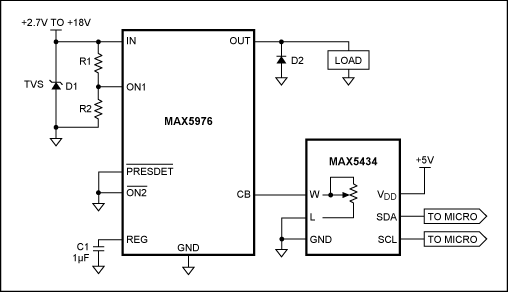
For a highly configurable overcurrent protection circuit, combine an integrated load switch with a digital potentiometer such as the MAX5434. This configuration allows a microcontroller (or manufacturing fixture) to program the overcurrent limit, as needed, without changing physical components. Figure 4 shows this application circuit.

Figure 4. The MAX5976 combined with a nonvolatile digital potentiometer, the MAX5434, for programmable overcurrent limit.
In applications where thermal constraints are critical, a negative temperature coefficient (NTC) thermistor can be used to set the current limit. The NTC thermistor provides a protection threshold that automatically decreases when the load begins to overheat, thereby preventing an incipient fault from worsening beyond recovery.
Conclusion
Because the MAX5976 and similar devices use a single resistor to set soft-start and overcurrent protection levels, simple changes to the basic application circuit can accommodate complex loads with widely varying startup and running current requirements. It is easy to combine the high level of integration and performance of integrated load switches with sophisticated state-dependent overcurrent protection.


