Multi-Chemistry Battery Charger Supports Maximum Power Point Tracking for Solar Panels
Multi-Chemistry Battery Charger Supports Maximum Power Point Tracking for Solar Panels
2017-04-01
The LTC4015 is a versatile synchronous step-down charger capable of supporting a variety of battery chemistries including lead-acid, Li-ion and LiFePO4. The LTC4015 features an extensive list of battery charging functions, including coulomb counting and an array of battery and system monitor capabilities. However, this article focuses on its input control loop, which enables solar panel maximum power point tracking (MPPT) functionality.
For readers who have not yet encountered the general concept of MPPT, or could use a knowledge refresh, visit "Techniques to Maximize Solar Panel Power Output". Regardless of your general knowledge of MPPT, to understand the LTC4015’s implementation, it is important to understand the LTC4015’s multi-control-loop operation.
Basic Device Operation
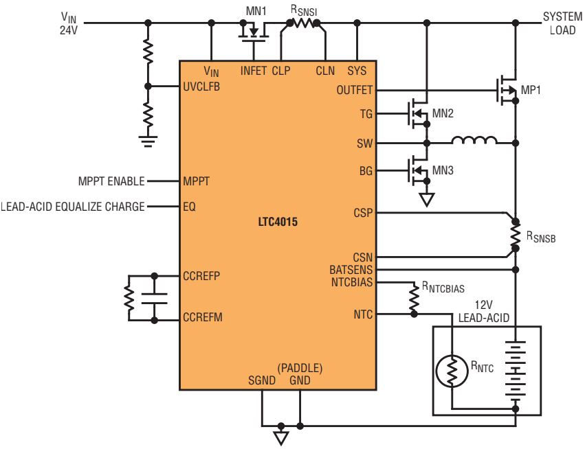
The LTC4015 charges batteries with a peak current mode synchronous step-down controller driving MN2 and MN3 (see Figure 1). The controller can regulate four parameters: input voltage (using the UVCLFB pin), input current (CLP and CLN), battery charge voltage (BATSENS) and battery charge current (CSP and CSN). Both peak inductor current control and battery charge current regulation are accomplished with sense resistor RSNSB. In addition to these two functions, RSNSB allows the LTC4015 to monitor battery charge and discharge current, battery ESR and battery coulomb count. The input voltage regulation is an integral part of MPPT operation and is discussed in detail in the next section.

Figure 1. Simplified LTC4015 application topology (not necessarily optimized for solar panel input).
The LTC4015 uses an ideal diode-OR PowerPath architecture to seamlessly interface both the input supply and the battery to the system load. Ideal diode MN1 connects VIN to VSYS if VIN is larger than VCSP (battery voltage) while MP1 connects the battery to VSYS if VCSP is larger than VIN. In addition to powering the system from VIN, the two diode controllers work with the charger to provide power from the battery to the system without back driving VIN and guarantee that power is available to the system even if there is insufficient or absent power from VIN.
When limited power is available to the switching charger because either the programmed input current limit (input current regulation) or input undervoltage limit (input voltage regulation) is active, charge current is automatically reduced to prioritize power delivery to the system load. However, it is important to note that the LTC4015 only limits charge current, but does not limit current from the input to the system load—if the system load alone requires more power than is available from the input after charge current has been reduced to zero, VSYS must fall to the battery voltage in order for the battery to provide supplemental power.
This is important for MPPT operation. The LTC4015 effectively uses its ability to manipulate charge current to regulate both input current and input voltage. In other words, if the input voltage decreases enough such that the UVCLFB pin voltage falls below its DAC-programmed servo voltage, then charge current is reduced in an attempt to maintain that input voltage level. Likewise, if the input current starts to exceed the DAC-programmed input current limit, then charge current is reduced in an attempt to maintain that input current level. However, if charge current is reduced to zero, the LTC4015 loses its ability to further affect input current or input voltage. Consider LTC4015 MPPT operation in more detail to understand why these issues matter.
MPPT Operation
The LTC4015 maximum power point tracking algorithm performs a periodic global search as well as a continuous local dither to ensure that the solar panel powering the system remains at its peak power operating condition. The global search is necessary to ensure that the continuous dithering algorithm does not get stuck at a local maximum power point. Depending on the exact panel construction, this can occur during partial shading conditions.
Both the local dither and global search make use of the LTC4015 input voltage regulation function called UVCL, or undervoltage current limit. The UVCL control loop prevents a resistive or current limited input power source from falling too low (e.g., below the undervoltage lockout, UVLO threshold) by automatically reducing charge current as VIN (observed at the UVCLFB pin using a VIN voltage divider) drops to a programmable level (VIN_UVCL_SETTING).
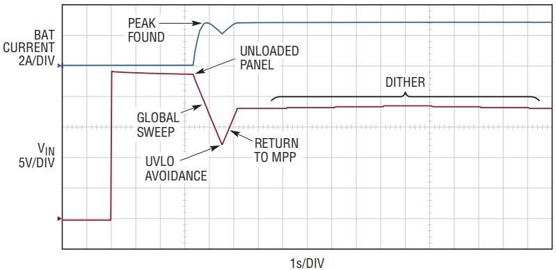
The global search steps VIN_UVCL_ SETTING through its full range of values, being careful to avoid pulling VIN below UVLO or VIN_DUVLO, the differential undervoltage lockout. The differential UVLO condition is met if the input voltage falls to within about 100mV of the battery voltage. At each VIN_UVCL_SETTING, the charge current is measured. When the sweep is complete, the LTC4015 applies the VIN_UVCL_SETTING value corresponding to the maximum measured battery charge current.
Because the battery voltage is low impedance and relatively stable throughout the sweep, maximum battery charge current corresponds well to maximum output power. Following the global search, small changes in maximum power are tracked by slowly—approximately once per second—dithering the VIN_UVCL_SETTING. The LTC4015 periodically—approximately once per fifteen minutes—performs a new global search of VIN_UVCL_SETTING values, applies the new maximum power point, and resumes dithering at that point. Figure 2 shows a typical MPPT global search followed by local dithering.

Figure 2. MPPT search algorithm.
The dithering algorithm begins by incrementing the VIN_UVCL_SETTING one step and measuring the new charge current. If the new charge current is greater than the previous measurement, then VIN_UVCL_ SETTING continues to be incremented approximately once per second until the charge current decreases or VIN_UVCL_ SETTING reaches full-scale, at which point the dither direction is reversed. Full-scale corresponds to VUVCLFB = 1.2V and an input voltage of 36.5V with the required UVCLFB MPPT resistor divider values. In the reverse direction, VIN_UVCL_SETTING is decremented approximately once per second until either the charge current decreases or the input voltage falls too close to the UVLO thresholds, at which point the dither direction is reversed again.
MPPT Special Considerations
While MPPT operation is fairly straightforward under most conditions, there are a few cases outside the norm. The LTC4015 steps outside the basic algorithm in these cases in an effort to maximize the time the panel spends at its true maximum power point.
Significant Changes In Charge Current During Dither
When the LTC4015 is using the dithering algorithm, if the battery charge current falls by 1% or more in a single dithering step, the dither direction reverses after only 7ms, rather than the normal one second. This maximizes the time spent at the highest power setting. Similarly, if the step-to-step change in charge current is more than ±25%, the algorithm repeats a global search without waiting the standard 15 minutes. The maximum global search repetition rate is once per five minutes.
Input Current Limit Setting
As mentioned above, the LTC4015 monitors the input voltage during the MPPT algorithm to ensure that it does not fall below one of the UVLO thresholds. Another criterion under constant monitoring is whether or not the LTC4015 is actually in UVCL regulation using the vin_uvcl_active bit of the digital telemetry system. Remember that four parameters can be regulated: input voltage (VIN_UVCL_SETTING), input current (IIN_LIMIT_SETTING), charge voltage (VCHARGE_SETTING) and charge current (ICHARGE_TARGET). For MPPT applications, it is recommend that the input current limit (IIN_LIMIT_SETTING) is set greater than or equal to the maximum short-circuit current capability of the solar panel. This ensures that input current regulation does not interfere with MPPT operation. However, two other regulation loops can take control: charge voltage and charge current.
Available Current Is Enough
During either the global search or dithering phase, if charge voltage or charge current regulation require less current than undervoltage current limit, UVCL, then it means that the solar panel can satisfy normal charging conditions at that particular VIN_UVCL_SETTING. At this point, the dither direction is reversed or the global search is stopped. During a global search, the VIN_UVCL_SETTING—which resulted in an exit from the UVCL regulation loop—likely corresponds to maximum charge current. If for some unusual reason it does not, the LTC4015 will ramp back to the VIN_UVCL_SETTING corresponding to maximum charge current.
Low Available Power
Another special case occurs when the maximum charge current, as measured by the completed global search, is below approximately 5% of full-scale, where full-scale corresponds to 32mV across RSNSB (e.g., 200mA for a 4A charger). In this case, the LTC4015 returns to the VIN_UVCL_SETTING found during the global search, but does not attempt to dither. At this charge current level, noise in individual ADC readings becomes significant and dithering potentially leads to erratic operation.
Even Lower Available Power
If the maximum charge current, as measured by the completed global search, is even lower, less than approximately 1% of full-scale (e.g., 40mA for a 4A charger, or a mere 320µV across RSNSB) then the LTC4015 has nearly lost its ability to control solar panel power. Nevertheless, one last attempt is made to maximize panel output power. The LTC4015 returns to a VIN_UVCL_SETTING that corresponds to 70% of the solar panel open-circuit voltage as measured when VIN_UVCL_ SETTING was at full-scale. Because solar panels typically produce maximum power with a voltage of 70%–80% of their open-circuit voltage, with power rolling off gently at lower panel voltages, this is a best attempt at maximizing power with minimal available information.
Potential Issues With Diode-OR Topology
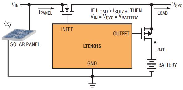
Depending on the specific application conditions, it is possible for the diode-OR topology (see Figure 1) to result in sub-optimal utilization of the solar panel power. Consider the simplified LTC4015 PowerPath architecture shown in Figure 3.

Figure 3. LTC4015 PowerPath architecture.
If the system load increases beyond the current capability of the solar panel, then both of the ideal diode controllers will turn on and MN1 and MP1 conduct to support the increased load. The solar panel output voltage collapses to the system load voltage, which collapses to the battery voltage.
Operation with the solar panel voltage equal to the battery voltage is unlikely to result in maximum power, but in most applications, this should not be a serious concern.
The solar panel should be sized such that on average, its power capacity is greater than the average load power. If this condition is not met, then the battery will not charge. Therefore, the scenario depicted in Figure 3 should not be typical.
Furthermore, any solar panel paired with the LTC4015 must have an open-circuit voltage of less than 40V to avoid violating the LTC4015’s absolute maximum ratings. Many commercially available panels that meet this requirement have a maximum power voltage of about 17V. When charging a 12V lead-acid battery, a 3S Li-ion stack (~11.7V), or a 4S Li-ion or LiFePO4 stack (~15.6V and 14V, respectively), the panel will likely still be operating above 75% or 80% of its maximum power. In other words, even if the difference between the maximum power voltage of the panel and the battery voltage is relatively small, performance is not significantly impacted. For panels whose maximum power voltage is not 17V, the same logic applies. If the maximum power voltage is relatively close to the typical battery voltage, then the brief time periods when the system load exceeds the panel current will not significantly impact performance. However, if this scenario is still a concern, there is a solution.
Battery Fed Topology
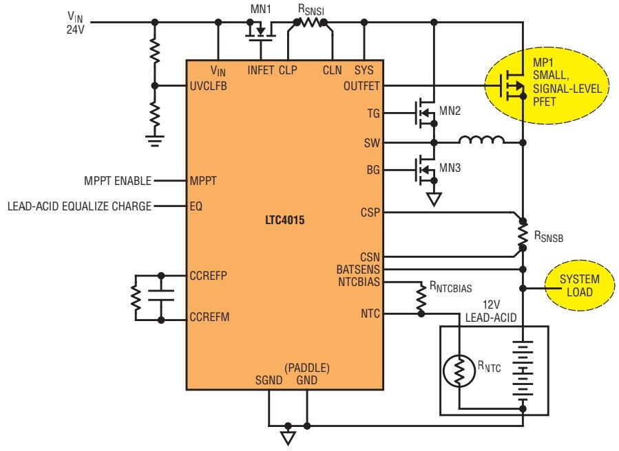
In order to ensure that the LTC4015 can always maintain complete control of solar panel power it is necessary to move the connection for the system load. See Figure 4 for a simplified schematic of this topology, which can be referred to as a battery fed topology. This configuration forces the load to share programmed charge current with the battery. In other words, the system load current directly subtracts from the programmed charge current and reduces battery current. If the system load exceeds the programmed charge current, then the battery simply supplies the additional current required.

Figure 4. Simplified LTC4015 battery fed topology.
The advantage of this topology is that the LTC4015 maximizes the combination of battery current and system load current. In other words, the LTC4015 maximizes the total output power. Because the input PowerPath only feeds current to the switching regulator, the LTC4015 has complete control over the input current. Since the LTC4015 output charges the battery and powers the load in this configuration, it can reduce output power to zero. The load remains supported by the battery under this condition.
Nevertheless, a battery fed topology does come with trade-offs, namely:
- The coulomb counter functionality of the LTC4015 is critically impaired because the LTC4015 cannot differentiate battery current from system load current. This inability to distinguish between the two currents has other consequences. The programmed charge current is no longer a fixed battery charge current. Instead, the battery charge current varies with system load. While charging, the digital telemetry system would be able to monitor and report on the sum of system load current and battery current, but no current readings would be available in “battery-only” operation (no input supply).
- This battery fed topology also impacts the termination algorithms, especially the current-based C/x termination. Instead of terminating when the battery current falls below a programmed threshold, the LTC4015 charge algorithm terminates when the combination of the load current and the battery current falls below that threshold. If the charge cycle were to terminate, then all system load current would be drawn from the battery until a recharge cycle begins.
- Finally, the ideal diode-OR PowerPath topology (Figure 1) provides power to the system as soon as input voltage is available even if the battery is heavily discharged. In the battery-fed topology of Figure 4, the input supply will need to charge the battery to a voltage greater than the minimum system voltage before the system can operate.
A corollary to this final disadvantage is that the battery must be able to supply the full load current at all times. Because the MPPT algorithm and the battery series resistance (BSR) algorithm will temporarily and periodically disable the switching regulator, the battery must be able to supply the full system load during these times. This is particularly critical when charging Li-ion chemistries. The LTC4015 Li-ion charge algorithms include a pre-charge phase. If a system load can discharge the battery below the pre-charge threshold, and that same load exceeds the pre-charge current, it is possible that the battery will be drained even with an input supply present. This could permanently damage the battery.
Because of these disadvantages, careful consideration should go into deciding between the standard diode-OR topology and the battery fed topology.
MPPT And Low Input Power
Despite its carefully designed MPPT algorithm (including the special corner cases described above) and ability to operate in different topologies, there is one scenario where the LTC4015 cannot maximize solar panel output regardless of topology.
The LTC4015 battery charger function requires a minimum amount of current to operate, which varies depending on the application (switching MOSFET selection, compensation, etc.) If the maximum input current available from the solar panel is above 2mA to 3mA but below the minimum level required to operate the charger (approximately in the range of 5mA to 20mA) then the battery may actually be discharged slightly by the charger.
Under these conditions—for example, a very dimly lit, but not completely dark, solar panel—the worst-case battery drain current is generally less than 10mA. The condition persists as long as the available input current remains in the range described. If the available input current falls lower, then the battery discharge returns to near normal battery-only mode levels—see the data sheet for details.
For typical solar panel applications, this condition is generally short-lived and infrequent, requiring no mitigation. For example, a short period of time before sunrise and after sunset may result in some extra battery drain. Nevertheless, as described in the data sheet, if this condition is a concern, it can be mitigated by disabling the charger (setting suspend_charger = 1) whenever the battery charge current falls below 1% of full-scale (IBAT ≤ 218) and retrying by writing suspend_charger = 0 periodically (e.g., every 60 seconds). Optionally, this retry can be limited to only occur when VIN is above a known threshold.
Conclusion
The LTC4015 can serve as the power management backbone of battery powered applications, and is especially adept at charging batteries and supporting loads when a solar panel is the input power supply. Its integrated ideal diode-OR controllers and ability to measure and regulate input current, battery current, input voltage and output voltage, enable it to maintain high battery charging performance and maximum power point tracking for solar panel input supplies.
关于作者
Trevor Barcelo拥有超过15年的凌力尔特公司工作经验,曾担任模拟IC设计工程师、设计经理和产品线经理。他的职业生涯始于凌力尔特位于美国加利福尼亚州米尔皮塔斯的总部,设计了LTC1733锂离子电池充电器。迁到公司的波士顿设计中心后,他继续设计电池充电器和USB电源管理器,包括


