I2C-Controlled Li-Ion Power Management IC with Integrated Power Devices Charges High Capacity Batteries from Any 5V Source While Keeping Cool
I²C-Controlled Li-Ion Power Management IC with Integrated Power Devices Charges High Capacity Batteries from Any 5V Source While Keeping Cool
2019-03-20
Designers of portable electronics are challenged to create devices that do everything while running endlessly on a single battery charge. While it is impossible to fully meet this challenge, each successive generation of batteries at least comes closer to that goal. With devices now sporting large vibrant touch-sensitive displays, multicore CPU and graphics processors, and an assortment of wireless modems for high speed communications anywhere on the planet, high battery capacity is essential. Battery manufacturers have met the demand with light weight, compact cells with capacities to over 30 watt-hours.
While USB has become the dominant standard for device interconnect, synchronization and data exchange, its power delivery capabilities have not kept pace with battery demands. USB 2.0 allows a maximum 2.5W load, while USB 3.0 extends the limit to 4.5W. Even with perfect efficiency and all power going directly to the battery, a full charge cycle via USB would require overnight and then some. Though USB is not suitable as a primary power source for large capacity batteries, it still has great value as an opportunistic power source to charge when and where possible, and to prevent battery drain when the device is tethered to a traditional computer.
The Best of Both Worlds
The LTC4155 is a monolithic switching battery charger that delivers 3.5A charge current efficiently in a compact PCB footprint. Figure 1 shows the required components in a typical application. The 2.25MHz switching frequency allows for a small inductor and bypass capacitors to minimize the overall PCB footprint.
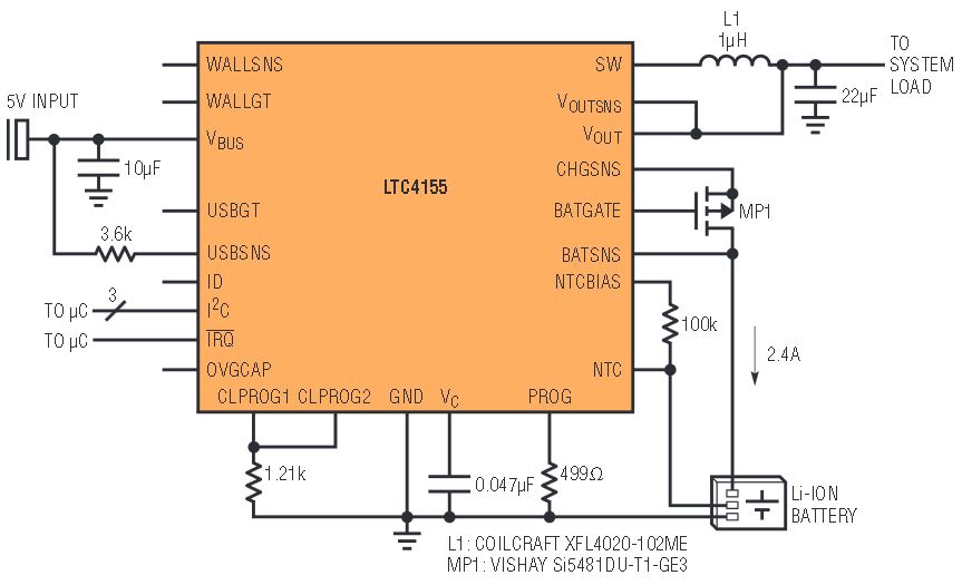
Figure 1. I2C controlled high power battery charger/USB power manager.
High efficiency (Figure 2) even at multi-amp charge rates is critical not only to make optimal use of available input power, but also to control power dissipation inside the portable device. The combination of high power dissipation and marginal thermal performance in a tightly enclosed space can make a device with a less efficient charging solution too warm to hold comfortably. To help keep things cool, the LTC4155’s integrated power switches feature an on-resistance well under 100mΩ.
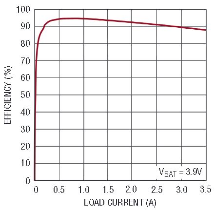
Figure 2. Switching regulator efficiency.
While the LTC4155’s power switches are sized to handle higher currents than available from USB, the LTC4155 remains fully USB compatible for opportunistic charging. Input current is automatically measured internally and limited to any of sixteen I2C user-selectable values. Of these settings, three correspond to guaranteed maximum limits of 100mA and 500mA for USB 2.0 and 900mA for USB 3.0. Automatic input current limiting can also be used with AC adapters or other sources by choosing any of the other current limit settings up to a maximum of 3A.
The LTC4155 supports a pin-programmable power-on default input current. For high power applications that do not require USB compatibility, a single resistor connected to the CLPROG1 pin programs a default power-on input current. This resistor is chosen to correspond to an initial current limit most appropriate to the particular application, intended power source capability, etc. After power-up, the input current limit can be modified under I2C control to any of the sixteen other available settings up to 3A.
For USB applications, the CLPROG1 and CLPROG2 pins can be connected together to program the LTC4155 to enforce USB current limit rules. The input current limit will default to 100mA upon application of external power. After successful enumeration with the USB host controller, the input current limit setting can be increased under I2C control to 500mA or 900mA as appropriate. Figure 3 shows the available current to the system load and battery charger. Note that the switching regulator output current is higher than the USB-limited input current. If the system detects that the power source is an AC adapter, dedicated USB charger, or other non-USB source, the input current limit setting can be increased under I2C control to any other setting up to 3A.
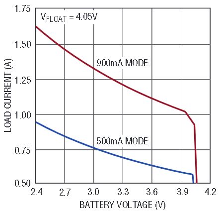
Figure 3. USB-compliant load current available before discharging battery.
Seamless Handling of Multiple Input Connectors
The LTC4155 optionally accepts input from two power sources, solving the challenge of intelligently routing power from two different physical connectors to the product. When both input sources are connected simultaneously, the decision of which source to use is based on a user-programmable priority. As long as each input voltage is within the valid operating range, either one may be selected without concern for which voltage is higher than the other. This allows, for instance, a 4.5V/2A AC adapter to be favored over a 5V/500mA USB port. If the USB connection is removed and a 5V/3A AC adapter is connected to the same port, the input source priority can be modified over I2C to switch to the new higher power source.
The LTC4155 supports independent I2C programmable input current limits for each of its two power inputs. When the higher priority input source is disconnected, charging can continue uninterrupted, with automatic reduction to the new lower maximum input current limit. No immediate attention is required from the system microcontroller.
Depending on the external components selected for the input multiplexer, overvoltage and reverse voltage protection up to ±77V can be easily implemented if required for the application. Additionally, the LTC4155 can produce a USB On-The-Go 5V current-limited supply to the USB connector using no additional external components.
Extensive Programmability and Telemetry for Advanced Charging Algorithms
The LTC4155 provides continuous I2C status reporting, allowing system software to have a complete view of the state of input power sources, fault conditions, battery charge cycle state, battery temperature, and several other parameters.
Key charge parameters can be changed under I2C control to implement customized charge algorithms. Unlike microcontroller-based or other programmable charge algorithms, all possible LTC4155 settings available under software I2C control are intrinsically safe for the battery. Float voltage can never be programmed above 4.2V or below 4.05V. Similarly, battery charge current is programmable to one of 15 possible settings, but software may never increase the limit above the level set by the designer—via a programming resistor chosen to match the battery capacity and maximum charge rate.
Continuous battery temperature data is available to system software to dynamically adapt system or charger behavior to manage extreme operational corners. For instance, float voltage and/or charge current may be reduced under I2C control to increase the battery safety margin at high ambient temperatures. Similarly, charge current or total system load current can be reduced in response to high temperature to reduce additional heating within the product enclosure.
Like all other aspects of battery charger programmability, the LTC4155 implements an intrinsically safe charging solution without (or despite) any software intervention. Battery charging is always paused when the cell temperature falls below 0°C or rises above 40°C. Additionally, a fault interrupt may be optionally generated whenever cell temperature rises above 60°C. Figure 4 shows the transfer function of the LTC4155 battery temperature data converter, with the autonomous charger cut-out temperature thresholds highlighted.
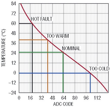
Figure 4. Transfer function of the LTC4155 battery temperature data converter, with the autonomous charger cut-out temperature thresholds highlighted.
PowerPath Instant-On Operation
Dead batteries can be especially troublesome in a traditional power architecture where most of the portable product is connected directly to the battery. When the battery voltage is too low for the system to run, the product may appear to be unresponsive even minutes after being connected to a source of input power—possibly generating unnecessary support phone calls. The problem is further compounded when the battery capacity is very large relative to the available charging current (e.g., a USB-powered system with a large capacity battery).
Analog Devices PowerPath™ products such as the LTC4155 decouple the system power rail from the battery to enable instant-on operation and solve the two most vexing problems caused by deeply discharged batteries.
The first problem is that charge current and system load become indistinguishable when the system power rail is connected directly to the battery. When the battery is deeply discharged, battery manufacturers recommend a greatly reduced initial charge current until the cell voltage reaches a safer level. This trickle charge current must be programmed to a safe level for the battery assuming minimum or no system load current.
Secondly, in a direct-connect battery system, if the system is operational during trickle charging, a significant portion of the charge current intended for the battery is shunted to the system rail. The resulting reduced battery charge current extends recovery time proportionately. A sizable system load can cause the net battery current to reverse, further discharging the battery. For the duration of this low battery condition, the portable system may not be able to respond to the user due to insufficient voltage on the system power supply rail. The duration of unresponsiveness is multiplied by at least a factor of 10 because of the reduced power available to the common-connected battery and system power rail.
The LTC4155 delivers 3.5V to the system rail when the battery is deeply discharged to enable instant start-up. As the battery voltage rises during the precharging phase, the LTC4155 seamlessly and automatically transitions to a higher efficiency mode to speed charging and minimize heat production. Figure 5 shows the voltage available to the system power rail as a function of battery voltage.
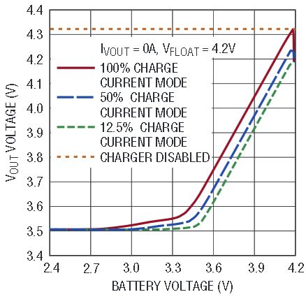
Figure 5. VOUT voltage vs battery voltage.
The LTC4155 battery charge current is programmed independently from the input current limit to decouple battery charge current constraints from input power constraints. The input current limit can be programmed based only on the limitations of the input supply. Similarly, the battery charge current can be programmed based only on the battery capacity. The LTC4155 always enforces input current limit and prioritizes power to the system load over battery charging if necessary.
Robust in the Face of Non-Ideal Sources
The LTC4155 features automatic reduction of input current when the input voltage begins to drop to an unacceptable level. At high charge current levels, this can happen when connections are made through undersized wire, to an undersized adapter, through connectors with mild corrosion, or any number of conditions outside the usual design envelope.
Without intervention, the input voltage to the IC would continue to drop, eventually falling below the undervoltage lockout threshold. The IC would then shut down, allowing the input voltage to recover and restart the whole cycle. The LTC4155 makes the best of a bad situation. As the input voltage falls to 4.3V, the LTC4155 smoothly reduces its input power by whatever amount is necessary to prevent further decay of the input voltage. In this mode the current delivered to the system load and battery is less than the programmed amount, but more than would be available if the input voltage oscillation were allowed to continue. Additionally, the LTC4155 produces an I2C status report and optional interrupt signal to alert the system that corrective or diagnostic action may need to be undertaken by the end user to restore maximum charge current capability.
Conclusion
The LTC4155 combines high current capability and efficiency with a small monolithic PCB footprint, ideal for portable devices with large lithium batteries where board space is at a premium, and heat and charge time are the enemy. USB-compatible input current limit settings further extend versatility to allow opportunistic charging from ubiquitous but lower power sources. Extensive telemetry allows for custom behavior based on changing environmental or application conditions without compromising autonomous battery safety. Uninterrupted power is delivered to the system rail despite common problems such as a deeply discharged battery or a resistive undersized input power cable. The LTC4155 is available in a 28-lead 4mm × 5mm QFN package.


