摘要
The DS186xEVKIT is an evaluation kit designed for the DS1854, DS1857, DS1858, DS1859, and DS1856. This application note describes how to use the DS186xEVKIT with the DS1856, a part that was introduced after the EV Kit was developed.
Introduction
This application note describes how to adapt the DS185xEVKITto evaluate the DS1856. This EV Kit consists of hardware and software to interface with the DS1854, DS1857, DS1858, DS1859, and DS1856. When the DS185xEVKIT was designed, however, the DS1856 did not exist. Consequently, DS1856 evaluation is not described in the supplied EV Kit documentation. But using the latest software and following the directions given in this application note, the DS185xEVKIT can be used to evaluate the DS1856.
Hardware
The hardware supplied with the EV Kit has jumper tables and probe clips labeled on the PCB silk screen only for the DS1854, DS1857, and the DS1858. This is not a problem. The hardware is very versatile and can easily accommodate the DS1856 simply by configuring the hardware similar to the DS1858.
To evaluate the DS1856, use the tables and text for the DS1858. The only exception to using the DS1858 markings is that the WP (WPEN) pin does not exist on the DS1856. Therefore, the jumper on the PCB for WP may be left in any state, including floating.
Software
The latest version of the EV Kit software, which includes DS1856 support, can be downloaded.
Besides adding DS1856 support, several other software improvements allow easier evaluation of DS185X parts. If the application is started and the DS1856 is not an option in the "Select a Device..." window, then a new version of the software must be obtained. Software version V1.4 and newer includes DS1856 support. A list of changes and improvements can be found in the readme.txt file available with the software on the FTP site.
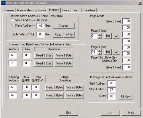
Several new software features and updates are noteworthy. First, in the General page (Figure 1), a Memory Configuration box has been added to control the ADEN bit (PW2 clearance is required). Second, two other boxes have been added to program the passwords (PW1/PW2) and grant clearance by entering password entry bytes. Third, in the Memory page (Figure 2), the Table Select box has been changed to accommodate more tables and allow easier data entry.
Evaluating the DS1856
The test points and jumpers for the DS1856 are labeled in the "58" column of the printed tables on the EV Kit board. The DS1856's outputs (OUT1 and OUT2) are connected to the corresponding jumpers as well as the test points on the kit. To prevent bus conflicts, jumpers on output pins should be properly configured prior to powering up the kit. IN1 and IN2, however, do need to be in a well-defined logic state for the DS1856 and should be jumped to VCC or ground.

Figure 1. General page.

Figure 2. Memory page.
Digital Outputs
OUT1 and OUT2 can be sampled at the test points with a multimeter or an oscilloscope for most evaluation purposes. The outputs are open drain, so a pullup resistor (not provided on the PC board) must be used to output a high state. The test points also provide an easy way to connect to external circuitry for further evaluation.
Resistor Terminals
The resistor test points can be used to attach the DS1856's resistors to external circuitry for evaluating the device. If the low terminal requires a connection to ground or the high terminal requires a connection to VCC, connection can be made by changing the jumper positions in the jumper block. If the resistor values are not changing as expected with adjustments made in the software, then check the following software settings. First, to change the resistor settings manually, the DS1856 must have PW2 clearance (granted in the General page). Second, the TEN bit (in the mode byte) must be high, and this also requires PW2 clearance. Lastly, the SoftHiz bit [HIZCO] must be low and requires at least PW1 clearance.
Monitor Inputs
Typically, the monitor inputs are driven by a bench supply during evaluation. The software displays the monitor pins' voltages on the Real-Time page as well as the General page. Precautions should be taken not to exceed the absolute maximum ratings prescribed by the evaluation part's datasheet.
Conclusion
This application note describes how to adapt the DS185xEVKIT to evaluate the DS1856. Using the latest version of the software and re-orienting jumpers on the hardware, the DS1856 can be evaluated using the existing EV Kit. The DS1856 and the other DS185X family members can also be evaluated more easily using the updated version of the software.


