High Voltage Surge Stoppers Ease MIL-STD-1275D Compliance by Replacing Bulky Passive Components
High Voltage Surge Stoppers Ease MIL-STD-1275D Compliance by Replacing Bulky Passive Components
by
Dan Eddleman
2014-04-01
Electronics in a military vehicle face a unique set of challenges, chief among them operation from a perverse power supply. Recognizing the difficult power supply fluctuations that occur in the field, the US Department of Defense created MIL-STD-1275D to set down the requirements of electrical systems powered from a military vehicle’s 28V supply. Designing systems to withstand MIL-STD-1275D’s surge and related transients traditionally requires large and expensive passive components. Linear Technology’s surge stopper product line is well suited to protecting systems from this type of surge while reducing the cost and solution size.
MIL-STD-1275D Requirements
MIL-STD-1275D defines a variety of conditions, most importantly those of steady state operation, starting disturbances, spikes, surges, and ripple. MIL-STD-1275D lays down requirements for each of these conditions in three separate “modes of operation”: starting mode, normal operating mode, and generator-only mode.
Before describing the specifics of spikes, surges, ripple, and other requirements, let’s first look at the modes of operation. Not surprisingly, “starting mode” describes the conditions that occur when the engine is started; “normal mode” describes the conditions when the system is operating without any faults; and “generator-only” mode describes a particularly vicious circumstance where the battery has been disconnected and the generator is directly powering the electronics.
Generator-only mode is a challenging situation. Normally, a battery conceals the erratic nature of the generator by maintaining a relatively constant voltage despite the generator’s power fluctuations. Predictably, the limits set down for generator-only mode are worse than normal operating mode. For the most part, if the system operates through the generator-only mode conditions, it will have no difficulty with normal mode. (The one possible exception is that generator-only mode’s 500mΩ source impedance during a surge can ease the burden when compared with the 20mΩ source impedance in the normal operating mode.)
Steady-State
As with any standard, MIL-STD-1275D spells out conditions and requirements in detail. The purpose of this article is to present these requirements, and a proposed solution, in a more digestible form. It is recommended to refer to MIL-STD-1275D for more precise definitions and requirements.
MIL-STD-1275D defines steady-state as, “The condition in which circuit values remain essentially constant, occurring after all initial transients or fluctuating conditions have subsided. It is also definitive of the condition where, during normal system operation, only inherent or natural changes occur; (i.e., no malfunctions occur and no unanticipated changes are made to any part of the system).”
More simply, in steady-state the input voltage remains relatively constant.
As shown in Table 1, the steady-state input voltage range during normal operating mode ranges from 25V to 30V. During generator-only mode (the condition where the battery is disconnected), the steady-state voltage range is somewhat wider at 23V to 33V.
| Specification | Normal Operating Mode | Generator-only Mode |
| Steady State | 25V < VIN < 30V | 23V < VIN < 33V |
| Spikes | 250V, Max Energy=15mJ | Same as Normal Operating Mode |
| Surges | 40V Max, ~500ms, RIN = 20mΩ | 100V Max, ~500ms, RIN = 500mΩ |
| Ripple | Magnitude ±2V | Magnitude ±7V |
Spikes
Rather than quote the definition of a spike from MIL-STD-1275D, let’s instead look at the example in Figure 1. A spike is generally oscillatory (it rings) and decays to the steady-state voltage within 1ms. MIL-STD-1275D states that these spikes occur when reactive loads are switched, and may occur during events such as sounding the horn, operating the bilge pumps, starting and stopping the engine, or rotating the turret.
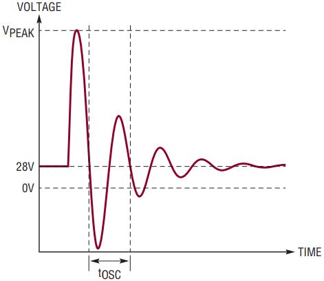
Figure 1. MIL-STD-1275D spike.
While that description is useful in understanding a spike, the actual requirements are defined by Figure 2 (for generator-only mode). Additionally, in subsection 5.3.2.3, “Voltage Spikes Imported into EDUT,” MIL-STD-1275D describes a recommended test setup as well as the required risetime and frequency of oscillation. An important fact to note is that the maximum energy is limited to 15mJ. The spike requirement for normal operating mode is similar to generator-only mode except that rather than a 100V limit at 1ms, the normal operating mode limit is 40V at 1ms.
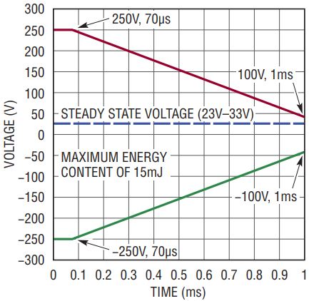
Figure 2. Envelope of spike in generator-only mode.
Surges
Spikes are transients that last less than 1ms; surges are transients that last longer. Figure 3 shows the limitations for generator-only mode. Note that the recommended test in MIL-STD-1275D specifies that five 100V pulses of 50ms duration should be applied at the system input with a 1s repeat time. Interestingly, the envelope of the surge condition shown in Figure 3 is more difficult to satisfy, as it does not return to 40V for a full 500ms. The solution shown in this article satisfies both of these conditions. Once again, the requirements for normal operating mode are easier; the surge envelope looks similar, except that it has a 40V maximum instead of 100V. The reader should refer to the actual specification for details not covered here.

Figure 3. Generator-only mode surge envelope.
Ripple
Ripple is the term used to refer to variations of the input voltage about the steady state DC voltage. It may be composed of frequencies from 50Hz to 200kHz. In generator-only mode, the ripple is as large as ±7V about the DC steady state voltage. In normal mode, it is somewhat lower, ±2V around the steady state DC voltage. The MIL-STD-1275D specification provides explicit test conditions and recommends a set of frequencies for testing.
Starting Mode
In addition to normal mode and generator-only mode, MIL-STD-1275D defines starting mode, which describes the voltage variations caused by the engine starter and cranking. Figure 4 appears in the MIL-STD-1275D specification. It begins at the steady-state DC voltage and then drops as low as 6V during the “Initial Engagement Surge.” Within one second it rises to the “Cranking Level” which has a 16V minimum voltage. It returns again to the steady state DC voltage within 30 seconds.

Figure 4. Starting disturbances.
Other Requirements
MIL-STD-1275D stipulates that the system withstand polarity reversal without harm. Such a condition can occur during a jump start, if the jumper cables are connected backwards.
MIL-STD-1275D in turn refers to another standard, MIL-STD-461—regarding electromagnetic compatibility requirements—which is beyond the scope of this article.
Surge Stopper Solution For MIL-STD-1275D Compliance
Linear Technology’s surge stopper products provide a compelling solution to MIL-STD-1275D compliance. Alternative designs typically use shunt clamps at the input, which can result in damage or blown fuses during sustained overvoltage conditions.
Rather than shunt high energy levels to ground using bulky passive components, high voltage surge stoppers such as the LTC4366 and LT4363 limit the output voltage using series MOSFETs when faced with input voltage spikes and surges. During normal operation, the MOSFET is fully enhanced to minimize the power dissipated in the MOSFET. When the input voltage rises during a surge or spike, a surge stopper regulates the output voltage to provide safe, uninterrupted power to the load. Current limit and timer features protect the external MOSFETs from more severe conditions.
Surge
In MIL-STD-1275D, the worst-case MOSFET power dissipation condition occurs during the 100V input surge. The circuit shown in Figure 5 regulates the output voltage to 44V. As a result, the circuit must drop 56V from the 100V input to the 44V output. In this MIL-STD-1275D solution, to increase power available at the output, two series MOSFETs are used. The first MOSFET’s source is regulated to 66V by the LTC4366, while the second MOSFET’s source is regulated to 44V by the LT4363. This reduces the power that must be dissipated in either MOSFET.
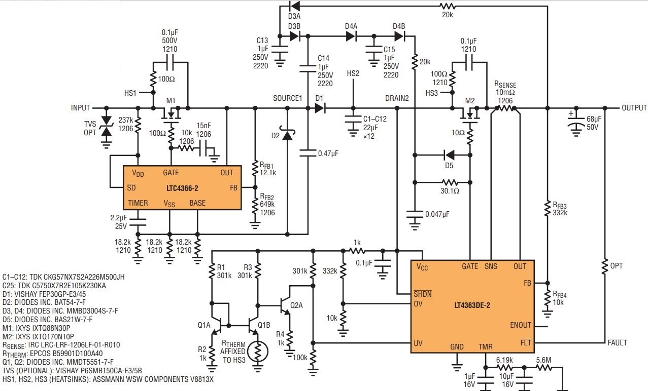
Figure 5. 4A/28V MIL-STD-1275D solution provides uninterrupted power to 4A loads while limiting the output voltage to 44V during MIL-STD-1275D 100V/500ms surges and ±250V spikes; powers 2.8A loads during ±7V ripple.
Figures 6 and 7 show the results measured during surge testing. The oscilloscope waveform in Figure 6 shows this circuit operating through the full 100V/500ms MIL-STD-1275D surge requirement described earlier. Figure 7 shows this circuit operating through the less stringent 100V/50ms pulses described in MIL-STD-1275D’s recommended tests.

Figure 6. MIL-STD-1275D 100V/500ms surge test.
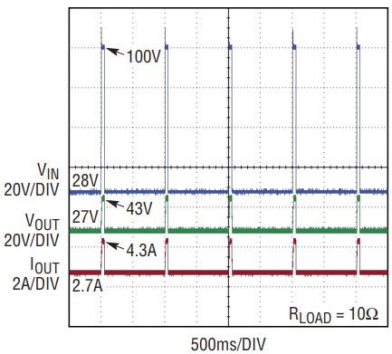
Figure 7. MIL-STD-1275D 100V/50ms surge repeated five times.
Spike
The +250V spike condition is handled by MOSFET M1, which is rated to withstand over 300V from drain to source. MIL-STD-1275D specifies that the input energy is limited to 15mJ, well within the capabilities of this MOSFET. Figure 8 shows that a +250V spike at the input is blocked from the output.
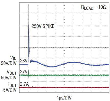
Figure 8. Positive input spike.
Similarly, the –250V spike test result is shown in Figure 9. In this condition, diode D1 is reverse biased during the –250V spike, blocking the spike from M2 and the output. D1 also provides reverse polarity protection, preventing negative input voltages from appearing at the output. (The LTC4366 surge stopper in front of D1 is capable of withstanding reverse voltages and the –250V spike without additional protection.)
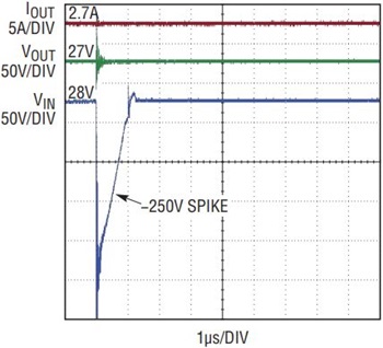
Figure 9. Negative input spike.
An optional bidirectional transient voltage suppressor (TVS) is present at the input to provide extra protection. Its 150V breakdown voltage does not affect circuit operation below 100V. For applications where a TVS is not desirable at the input, this optional component can be removed. Note that in Figures 8 and 9, the output voltage trace (VOUT) during the MIL-STD-1275D spike shows high frequency ringing, which is a measurement artifact of the large currents that flow in supply and ground traces when a 0.1µF test capacitor is discharged directly at the circuit input with all resistances and inductances minimized.
Ripple
Satisfying the ripple specification of MIL-STD-1275D requires a few more components. Diode D1 in combination with capacitors C1–C12 form an AC rectifier. This rectified signal appears at the DRAIN2 node.
The LT4363 in combination with sense resistor RSENSE limits the maximum current to 5A (typical). If the rising edge of the input ripple waveform attempts to pull up the output capacitor with more than 5A, the LT4363 momentarily limits the current by pulling down on M2’s gate.
To quickly restore the gate voltage, the small charge pump formed by components D3–D4, C13–C15 supplements the LT4363’s internal charge pump to quickly pull up MOSFET M2’s gate. Even so, the available load current must be reduced to 2.8A during this ripple condition. Figure 10 shows that the output remains powered during ripple testing.
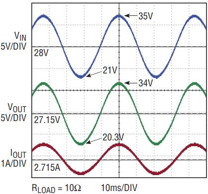
Figure 10. 14VP–P input ripple condition.
Thermal
Finally, thermal protection is implemented by components Q1, Q2, R1–R4 and thermistor RTHERM. If the temperature at M2’s heat sink (HS3) exceeds 105°C, the LT4363’s UV pin is pulled down by Q2A to force off MOSFET M2 and limit its maximum temperature.
It should be noted that with the specified components, this circuit is only guaranteed to work down to a minimum of 8V during the starting mode initial engagement surge rather than the minimum 6V specified in MIL-STD-1275D.
Typically, an EMI filter is placed at the input of MIL-STD-1275D compliant systems—while surge stoppers do not eliminate the need for filtering, their linear mode operation introduces no additional noise.
Conclusion
Linear Technology’s surge stopper products simplify MIL-STD-1275D compliance by using MOSFETs to block high voltage input surges and spikes while providing uninterrupted power to downstream circuitry. Blocking the voltage with series components avoids the blown fuses and damage that can occur when circuits attempt to shunt high energy to ground with bulky passive components. Additionally, this article has shown that even when the maximum transient power dissipation (such as during a high voltage surge) exceeds the capability of a single MOSFET, multiple series MOSFETs can be used to support higher power levels.
关于作者
Dan Eddleman是一名模拟工程师,在凌力尔特工作超过15年,曾担任过IC设计人员、新加坡IC设计中心经理和应用工程师。
他的职业生涯始于凌力尔特,设计了LTC2923和LTC2925电源跟踪控制器、LTC4355高压双通道理想二极管OR和LTC1546多协议收发器。他还是世界首款以太网供电控制器LTC4255的设计团队成员。他拥有两项与这些产品相关的专利。
随后
他的职业生涯始于凌力尔特,设计了LTC2923和LTC2925电源跟踪控制器、LTC4355高压双通道理想二极管OR和LTC1546多协议收发器。他还是世界首款以太网供电控制器LTC4255的设计团队成员。他拥有两项与这些产品相关的专利。
随后


