Choosing the Right Step-Up/Down Voltage Regulator for Portable Applications
摘要
窄带IoT(NB-IoT)和LoRa (远距离) IoT设备必须在小型电池供电的情况下工作数年。为降低功耗,必须谨慎选择每个电路模块,以及可在较宽输出电流范围内高效工作的升/降压调节器。MAX77827升/降压转换器拥有高效率、平稳切换、低静态电流和小尺寸,为NB-IoT和LoRa资产跟踪应用提供了理想电源方案。
Introduction
A popular power source for portable devices is a single lithium-ion cell with 4.2V at full charge and 2.8V at end of discharge. However, some functions within portable electronics, such as a SIM card and DSP, require 2.8V and 3.3V. These are normally provided by low noise LDOs. The LDOs inputs (VCC) must be at a slightly higher voltage than the highest LDO output. Hence, VCC ends up right in the middle of the lithium-ion battery’s range of operation. The use of a step-up/down voltage regulator, capable of operating from an input that can be higher or lower than the output, becomes necessary. Figure 1 shows the battery voltage (VBAT) as the power source for a typical portable design. Figure 1 shows the battery voltage (VBAT) as the power source for a typical portable design.
 Figure 1. LDOs input voltage set by a step-up/down converter.
In portable applications the voltage regulator efficiency is of the utmost importance, since higher efficiency translates into longer untethered operation. In this design solution we will review the available options, compare their performance, and determine the most efficient solution.
Bypass-Boost
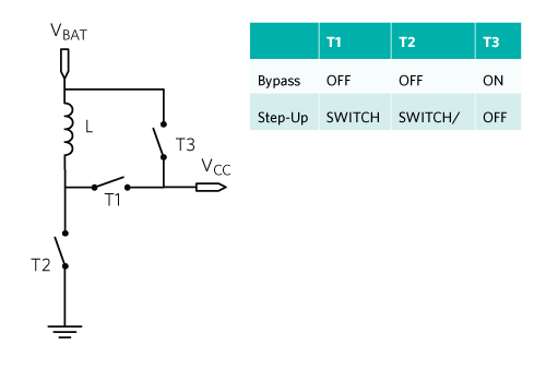
One way to solve the problem is to use a bypass-boost converter, namely a boost converter with an extra “pass” transistor integrated between the power source, VBAT, and the LDO input, VCC. Figure 2 shows the bypass-boost power train architecture and its operation table. Here the bypass transistor T3 accomplishes a “poor man’s” step-down operation.
 Figure 2. Bypass-boost power train and operation table.
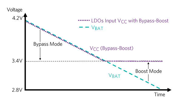
This architecture can only regulate VBAT voltages lower than the set VCC = 3.4V. For VBAT > 3.4V, the boost converter stops regulating and the pass transistor turns on, directly connecting VBAT to VCC. Figure 3 shows the battery profile discharging over time and the LDO input voltage for the bypass-boost architecture.
 Figure 3. LDOs input voltage profile with bypass-boost.
For the majority of the time (VBAT > 3.4V) the pass transistor in the bypass-boost architecture literally “passes the buck” to the LDOs downstream. The LDOs bear the task of regulating the high VBAT value down to their output set values. Since this regulation is linear the result is high power dissipation inside the LDO. This results in greater energy consumption and also requires a board design and IC selection capable of dissipating this energy.
Buck-Boost
In contrast to the bypass-boost architecture, a buck-boost converter used in this circuit will never stop regulating its output to 3.4V. In addition, the regulation is entirely switch mode, which provides high efficiency operation. Figure 4 shows the buck-boost power train architecture and its operation table.
 Figure 4. Buck-boost power train and operation table.
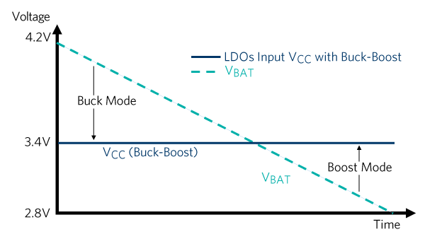
For VBAT > VCC, the IC regulates in buck (step-down) mode, while for VBAT < VCC it seamlessly transitions to boost (step-up) operation. The entire battery voltage range is covered in a switch-mode, high-efficiency fashion. Figure 5 shows the battery profile discharging over time and the LDO input voltage for the buck-boost architecture.
 Figure 5. Buck-boost power train and operation table.
Figure 6 superimposes the two modes of operation and highlights the section where the buck-boost has a clear advantage in terms of power dissipation. The shaded triangle represents the power lost in linear regulation by the bypass-boost operation.
 Figure 6. LDOs input voltage profile with buck-boost vs. bypass-boost.
Case Study
In this case study we compare the system efficiency (from VBAT to VOUT) of the MAX77801 buck-boost IC to a competitor’s bypass-boost IC. Each regulator feeds a single 3.3V LDO loaded with 500mA.
 Figure 7. Efficiency test setup.
Figure 8 shows the result of the comparison. Solid lines indicate efficiency and dotted lines show battery current consumption for each solution. As expected, the efficiency of the two architectures is similar when VBAT is below or near the LDO output voltage. Outside this range, and for the entire time VBAT is above the LDO output voltage, the efficiency of the buck-boost (above 90%) is far superior to that of the bypass-boost (as low as 75% with full battery). This superior performance is due to the ability of the buck-boost IC to supply power to the LDO in switch mode across the entire range of operation.
 Figure 8. Buck-boost vs. bypass-boost efficiency comparison.
Conclusion
The comparison of the buck-boost architecture to the bypass-boost architecture shows that, in principle, the buck-boost operates with superior efficiency. A practical comparison of the MAX77801 buck-boost solution versus a competitor’s bypass-boost architecture shows that in operation, there is an advantage of up to 17% efficiency for the Maxim device. Thus, the buck-boost IC is an ideal solution for power-stingy portable applications.


