摘要
There are many approaches for protecting a system against electrostatic discharge (ESD), surge current, overcurrent, undervoltage, overvoltage, and other disruptions to power. Industry, company, or regulatory standards such as UL®, USB, IEEE®, CSA, or IEC often require circuit protection. This application note discusses hot-swap ICs. Typical hot-swap circuits are described and the advantages of different hot-swap circuits are explained.
The Basics of Hot-Swap Circuits
Hot-swap circuits protect equipment, personnel, or both. Some power supplies, for example, have built-in and adjustable current limiting (standard in hot-swap circuits) that prevents damage to the power supply and the circuit being powered during a hot-swap event. Typical RAID and telecom systems have hot-swap capability for exchanging circuit boards or disk drives on the fly.
At a minimum, hot-swapping requires that you limit inrush current to prevent the possibility of a system-wide brownout when a large capacitive load is energized. Current limiting also helps reduce the size of the source power supply and limits electrical arcing at the connector contacts. Other hot-swap features include: low series resistance, circuit-breaker action, status indication, dual insertion-point detection, and power-good signaling.
Protection circuitry like hot-swap ICs adds components and cost while increasing the time to design and test a system. Nonetheless, those drawbacks must be weighed against the less-tangible costs (not always uppermost in a designer's mind) associated with unprotected systems: equipment damage, system downtime, personal injury and resulting lawsuits, replacement and repair costs, technician wages. This list could go on.
The introduction of hot-swap capability can immediately offset system costs by allowing a smaller main power supply. Reducing the level of surge current that a power supply must deliver allows smaller filter capacitors and a smaller power supply. Other benefits include smaller sized wiring and circuit traces, smaller and less expensive circuit connectors, and generally smaller components in the power path.
The simplest current-limiting component is the fuse, which can be used by itself or in combination with other protection elements. Because fuses are effective against overcurrent, they are either required (in circuits approved by UL, for instance) or included as a protection of last resort in the event of catastrophic failure.
For standard fuses, the major detraction is their one-time use. An alternative is the polyfuse, an otherwise similar device that physically expands and contracts according to the amount of heat generated by current flowing through it. The temperature-dependent polyfuse has a limited-voltage operating range, but it can reset itself which is an advantage over standard fuses.
Typical Hot-Swap Circuits
Capacitor-Zener-FET Combination
A common circuit in hot-swap applications is the capacitor-zener-FET combination (Figure 1a and 1b). This circuit limits inrush current by charging C1 across the gate-source junction of Q1. Assuming that C1 is discharged when power is applied, the circuit keeps Q1 off by acting as a short across the gate-source junction. As C1 charges, VGS increases and allows Q1 to turn on slowly. The size of C1 and the VGS characteristic of Q1 determine how quickly Q1 turns on and charges the load capacitor (C2).
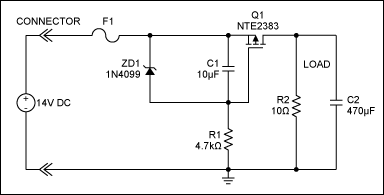
Figure 1a. A discrete "cap-zener-FET" hot-swap circuit uses the charge rate of C1 to control the turn-on of Q1. This is shown in the scope plot of Figure 1b.
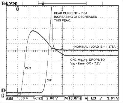
Figure 1b. CH1 is load current; CH2 is Q1 gate voltage.
In Figure 1a zener diode ZD1 prevents the Q1 gate-source junction from exceeding its maximum rating. (Note that the VGS maximum in Figure 1a (±20V) is too small to withstand 24V industrial or 48V telecom applications.) If power is cycled rapidly, the load capacitor can be discharged while C1 remains sufficiently charged to maintain Q1 on. That condition can diminish the current-limiting feature, allowing a large current surge when power is reinstated. There is another drawback of the capacitor-zener-FET topology: current limiting is active only during power-up and only if C1 is discharged. Once energized, the circuit cannot protect against overcurrent and short-circuit conditions. A fuse is typically employed for that purpose.
PNP Transistor and Current-Sense Resistor
Another circuit for hot-swap applications (Figure 2a and 2b) uses a PNP transistor (Q1) and a current-sense resistor (R1) to provide continuous current sensing and limiting. As power is applied, current flows through R1 and Q2 to the load. Current through R1 creates the VBE bias voltage for Q1. If the current is great enough to bias Q1 on, then Q1 limits conduction through Q2 to the load by reducing the gate-source voltage of Q2. Note that a zener diode could be added across Q2's gate-source junction (as in Figure 1a) to prevent overvoltage on Q2 and VCE breakdown on Q1.
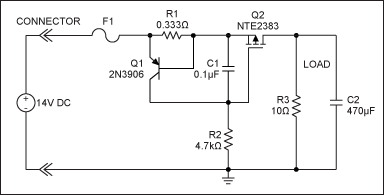
Figure 2a. Another hot-swap circuit implements current sensing and 2A limiting with a PNP transistor (Q1). This is illustrated by the turn-on waveforms in Figure 2b.
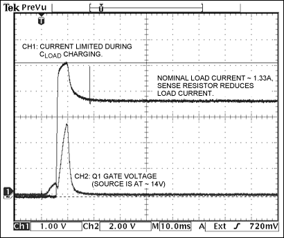
Figure 2b. CH1 is current; CH2 is Q2 gate voltage.
An advantage of this circuit, unlike Figure 1a, is that current limiting is always enabled. This positive feature comes with a disadvantage: added power dissipation of R1 in series with the load. Also, the current limit can change as much as ±20% as a consequence of Q1's VBE variation over the temperature range from -40°C to +85°C. The zener diode in Figure 1a (and in Figure 2a, if added) should be small enough to protect the transistors, but large enough to allow the FET its full conduction range for ID while minimizing RDS(ON).
Advantages of Hot-Swap Circuits
IC-based hot-swap circuits offer many features in a small package and they require few external components. Figure 3a, for example, shows a low-voltage hot-swap application that requires only a current-sense resistor (R1) and series-pass element (Q1) for operation between 2.7V to 13.2V. The circuit offers inrush-current limiting (Figure 3b) and dual overcurrent fault protection, which consists of a fast response from the MAX4370 for high-amplitude circuit faults and a slow response for low-amplitude, disruptive overcurrent conditions.
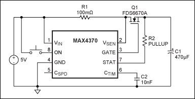
Figure 3a. An IC-based hot-swap circuit using the MAX4370 offers better accuracy and uses few components.
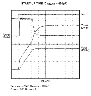
Figure 3b. Note the limiting of ILOAD in a scope plot of the start-up waveforms. Data were generated with the MAX4370 hot-swap controller.
The MAX4370 has continuous current monitoring, as does the circuit of Figure 2a. The MAX4370-based version, however, has better initial accuracy and better temperature performance than the discrete version of Figure 2a. The PNP transistor in Figure 2a has a typical VBE drift of 2mV/°C, producing an approximate output change of ±120mV for temperature excursions within the range from -40°C to +85°C, starting from +25°C. The MAX4370 in Figure 3a, however, exhibits maximum drifts of ±6.5mV and ±20mV for the slow and fast current-limit comparators.
Transistors seldom specify VBE, but the MAX4370 has a voltage trip point that is well defined and much lower: 50mVTH, which is one-twelfth that of VBE at 0.6V. The result is a smaller sense resistor with less power loss. Moreover, the IC-based circuits do what the Figure 1a and 2a circuits cannot:
- Utilize lower cost n-channel MOSFETs
- Provide a status output
- Respond to low- and high-level fault conditions
- Provide a power-control pin (ON) suitable for load control or for pin detection with dual card insertion
- Provide autoretry and latch-fault management
- Provide an I²C-compatible interface
- Detect overtemperature and provide thermal shutdown
- Support multivoltage systems and specific applications like the PCI-Express® standard
The MAX4370 in Figure 3a also acts as a circuit breaker by latching load power off when a fault is detected. If an application requires autoretry or 15V inductive-kickback protection, you can substitute a MAX4272 or MAX4273 hot-swap controller.
High-voltage, IC-based hot-swap circuits can save space versus a discrete circuit. A SOT23-sized controller like the MAX5902 (Figures 4a and 4b) operates from 9V to 72V and requires only one external p-channel MOSFET (Q1) for basic operation. The circuit does not require a current-sense resistor to limit in-rush current or detect fault conditions. Instead, it employs as a current-sense element the RDS(ON) of a p-channel MOSFET (Q1).
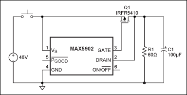
Figure 4a. A dedicated hot-swap IC like the MAX5902 simplifies the application.
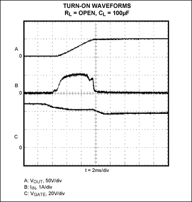
Figure 4b. Turn-on waveforms are illustrated at 2ms/div. Data were generated with the MAX5902.
The MAX5902 controller keeps the MOSFET off when power is first applied. It maintains that off state indefinitely if the ON/OFF pin is held low, if the supply voltage is below the undervoltage lockout (UVLO) level, or if the die temperature exceeds +125°C (typ). If none of those conditions applies when the built-in turn-on delay expires (150ms, typ), the MAX5902 gradually turns on Q1. During this turn-on phase, the controller slowly enhances Q1, allowing voltage on the load (drain of Q1) to rise at a typical rate of 9V/ms.
Inrush current to the load is, therefore, limited to a level proportional to the load capacitance and the constant slew rate: ILIMIT (typ) = CLOAD × 9V/ms. After Q1 is fully enhanced and the load voltage is settled to its final value, the voltage drop across Q1 (ILOAD × RDS(ON)) is monitored for faults by the MAX5902. If the voltage drop exceeds the circuit-breaker's threshold, the controller turns Q1 off and immediately disconnects the load.
Unlike discrete-component circuits, the Figure 4a circuit features thermal-shutdown protection, UVLO protection, shutdown with the ON/OFF pin, and a power-good (PGOOD) status signal. The MAX5902 is available with or without a circuit-breaker function, and the circuit breaker is available with either an autoretry or a latched-off option.
To implement a system that accepts -9V to -100V, like -48V for a telecom application, substitute a MAX5900 or MAX5901 hot-swap controller for the MAX5902.
A single IC-based hot-swap controller can replace many discrete components and microprocessor supervisory ICs; it can also support multiple outputs and add sequencing/tracking capabilities. The MAX5927, a quad hot-swap controller, protects multisupply systems like portable computer devices. It allows the designer to configure input voltage rails to turn on/off sequentially, track each other, or operate independently.
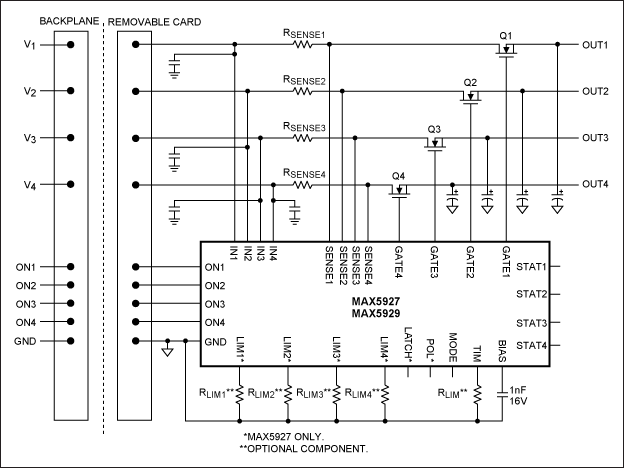
Figure 5. A single hot-swap IC controls four different rails in a multi-supply application.
In more complex applications where several rails should be protected and specific requirements should be considered, a circuit designed with discrete components is not an option. IC-based hot-swap controllers designed for specific applications offer the desired features and control the overall system as required. The MAX5915/MAX5916, for example, allow safe insertion and removal of PCI® cards into live PCI slots or backplane. These ICs provide independent power controls for 3.3V, 5V, ±12V, and 3.3V auxiliary supplies of two PCI cards with a few external components. The MAX5943 provides a simple, yet reliable, solution for safe insertion and removal of FireWire® peripherals into a live FireWire port. This IC requires only two external MOSFETs and a sense resistor for basic operation, while it provides a fully integrated power-management control for FireWire applications.
Summary
IC hot-swap controllers offer many advantages over their discrete counterparts. Though discrete circuits cost less than hot-swap ICs, they can be more costly to the overall system in terms of robustness, downtime, and repair costs. In fact, larger primary power supplies and more robust wiring and connectors are just some of the tangible costs associated with the discrete-components. Hot-swap ICs offer advantages that discrete designs lack: a STATUS output, thermal shutdown, UVLO, and shutdown (on/off) inputs for load control and for the detection of circuit-board insertion.
关联至此文章
产品
双路PCI 2.2热插拔控制器
双路PCI 2.2热插拔控制器
+72V、SOT23/TDFN封装、Simple Swapper热插拔控制器
3V至12V、限流型、热插拔控制器,带有自动重试以及DualSpeed/BiLevel故障保护
双路PCI 2.2热插拔控制器
双路PCI 2.2热插拔控制器
电流调节热插拔控制器,带有DualSpeed/BiLevel故障保护
-100V、SOT23/TDFN封装、Simple Swapper热插拔控制器
3V至12V、限流型、热插拔控制器,带有自动重试以及DualSpeed/BiLevel故障保护
-100V、SOT23/TDFN封装、Simple Swapper热插拔控制器
低电压、四路、热插拔控制器/供电排序器
FireWire限流器与低压差“或”逻辑开关控制器


