
概览
设计资源
描述
MAXREFDES1302 is a reference design for TWS application based on the Analog Devices 1-Wire® solution. This reference design provides power and battery management solutions for the TWS cradle and earbuds (right & left), including battery charging, battery monitoring, and power management. An OLED display is mounted on the cradle side to display earbud connection state, state-of-charge (SOC in %) and remaining capacity (CAP in mAh) of batteries of the cradle and earbuds. A serial port monitor can also be used to show such information.
On the cradle side, USB Type-C® charging is realized by the MAX77751, which integrates a 3.15A switch charger and BC1.2. Also, USB Type-C Configuration Channel (CC) detection pins of the MAX77751 enable automatic USB Type-C power source detection and input current limit configuration. The MAX17262 is used to monitor battery remaining capacity and state-of-charge of the batteries. The MAX17262 implements the Analog Devices ModelGauge™ m5 EZ algorithm and features internal current measurement for up to 3.1A pulse currents. The MAX17224 is an ultra-low quiescent current boost DC-DC converter with a 225mA/0.5A/1A peak inductor current limit and True Shutdown™. The MAX38640 is nanoPower family of ultra-low 330nA quiescent current buck (step-down) DC-DC converters that operate from 1.8V to 5.5V input voltage and support load currents of up to 175mA with peak efficiency of 96%. While in shutdown, there is only 5nA of shutdown current. The MAX32655 microcontroller is used to configure the fuel gauge, 1-Wire communication, and 1-Wire power transfer.
On the earbud side, the DS2488 provides a cost-effective solution for power transfer and communication between the TWS cradle and earbuds. The DS2488 is a low-cost simple bridge device with a single dedicated contact on each side of the bridge which enables power delivery for the battery charging, small message exchange, and the state reporting between two microcontroller-based subsystems. The battery management system for earbuds consists of the MAX77734 and MAX17262. The MAX77734 provides highly integrated battery charging and power supply solutions for the low-power applications where size and efficiency are critical. The MAX32655 on the earbud side configures the MAX77734, MAX17262, DS2488 and MAX98050. The MAX98050 is a low-power, high-performance audio codec with integrated low-latency digital filters for wireless hearables, headsets, and headphones.
优势和特点
Features
- Integrated solution
- Small size
- Low power
- High accuracy
- Low cost
详情
MAXREFDES1302 is a reference design for TWS application based on the Analog Devices 1-Wire® solution. This reference design provides power and battery management solutions for the TWS cradle and earbuds (right & left), including battery charging, battery monitoring, and power management. An OLED display is mounted on the cradle side to display earbud connection state, state-of-charge (SOC in %) and remaining capacity (CAP in mAh) of batteries of the cradle and earbuds. A serial port monitor can also be used to show such information.
On the cradle side, USB Type-C® charging is realized by the MAX77751, which integrates a 3.15A switch charger and BC1.2. Also, USB Type-C Configuration Channel (CC) detection pins of the MAX77751 enable automatic USB Type-C power source detection and input current limit configuration. The MAX17262 is used to monitor battery remaining capacity and state-of-charge of the batteries. The MAX17262 implements the Analog Devices ModelGauge™ m5 EZ algorithm and features internal current measurement for up to 3.1A pulse currents. The MAX17224 is an ultra-low quiescent current boost DC-DC converter with a 225mA/0.5A/1A peak inductor current limit and True Shutdown™. The MAX38640 is nanoPower family of ultra-low 330nA quiescent current buck (stepdown) DC-DC converters that operate from 1.8V to 5.5V input voltage and support load currents of up to 175mA with peak efficiency of 96%. While in shutdown, there is only 5nA of shutdown current. The MAX32655 microcontroller is used to configure the fuel gauge, 1-Wire communication, and 1-Wire power transfer.
On the earbud side, the DS2488 provides a cost-effective solution for power transfer and communication between the TWS cradle and earbuds. The DS2488 is a low-cost simple bridge device with a single dedicated contact on each side of the bridge which enables power delivery for the battery charging, small message exchange, and the state reporting between two microcontroller-based subsystems. The battery management system for earbuds consists of the MAX77734 and MAX17262. The MAX77734 provides highly integrated battery charging and power supply solutions for the low-power applications where size and efficiency are critical. The MAX32655 on the earbud side configures the MAX77734, MAX17262, DS2488 and MAX98050. The MAX98050 is a low-power, high-performance audio codec with integrated low-latency digital filters for wireless hearables, headsets, and headphones.
Main features and benefits:
- Integrated solution
- Small size
- Low power
- High accuracy
- Low cost
Table 1 and Table 2 provide an overview of the Cradle design specification and the Earbuds design specification, respectively.
| PARAMETER | SYMBOL | MIN | MAX |
| Battery Voltage | BAT | 3.1V | 4.6V |
| USB Input Voltage | CHGIN | 4.8V | 5.2V |
| Boost 5V Output | 5V | 4.8V | 5.2V |
| Buck 3.3V Output | 3V3 | 3.2V | 3.4V |
| PARAMETER | SYMBOL | MIN | MAX |
| Battery Voltage | VBAT | 3.3V | 4.6V |
| LDO 3.3V Output | VCC_3.3 | 3.2V | 3.4V |
| MCU 1.8V Output | VCC_1.8 | 1.7V | 1.9V |
| Buck 3.3V Output | 3V3 | 3.2V | 3.4V |
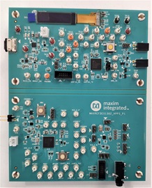
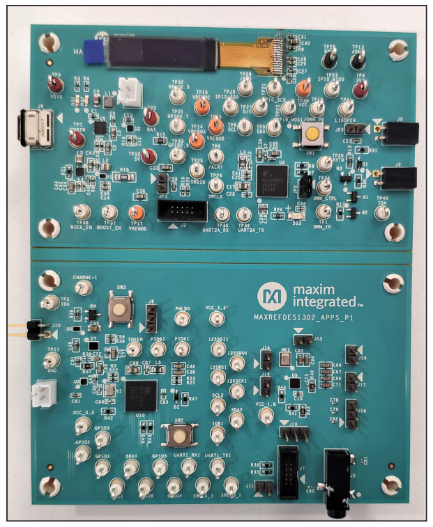
This document describes the hardware shown in the Figure 1 and provides a detailed technical guide to design a 1-Wire TWS power management system, which has a small size, low power consumption, high efficiency, and outstanding accuracy with low cost. The design is fully tested, and technical details are shown in the following sections.
The power supply system for TWS applications has the following features:
- Small size – The size of the earbuds should be as small as possible. Since more functions are needed to be implemented into the device, the size of device components plays an increasingly important role in the design. The diversity of the functions provided by the device directly depends on the number of components the device could contain.
- Low power – The batteries provide the power for the whole system. Because of the limited size and energy density of the battery, low power systems generally have longer service life. Wearable devices usually have two operation modes: standby mode and operation mode. The working time of the most devices in standby mode accounts for over 90%, so it is important to reduce the standby current.
- High efficiency – In the latest TWS applications, earbuds are typically charged by the cradle. However, sometimes the battery voltage of the cradle may be larger or smaller than the battery voltage of earbuds. High VIN/VOUT ratio of earbuds charger may result in the loss of output energy on the cradle side, and generated heat on the earbud side.
- High Accuracy – The earbuds require highly accurate battery state-of-charge measurement, which is required by the market.
- Low Cost – The wearable headphones must be competitive in price, which requires the cost of the whole system to be as low as possible.
This power management platform includes a cradle, earbuds, and a power delivery path.
Step 1: Select Power Delivery Solution
For TWS applications, the cradle needs to supply power to the earbuds. At the same time, it is necessary to communicate between the two to realize the message exchange and the real-time battery state update. Since the size and cost are significantly important in the TWS solutions, 1-Wire dual-port link IC-DS2488 is selected to meet the design requirement. DS2488 provides a cost-effective solution for the power transfer and communication between the TWS cradle and earbuds. It is a simple bridge device with a single dedicated contact on each side of the bridge which enables power delivery for the battery charging, small message exchange, and the state reporting between two microcontroller-based subsystems.
Step 2: Select Cradle Power Management Solution
The cradle obtains power from USB and outputs 5V for 1-Wire charging. The 3.15A USB Type-C autonomous charger, MAX77751, charges the 1-Cell Li+ battery on the cradle side. The battery is monitored by the MAX17262, which is an ultra-low power fuel-gauge IC with integrated internal current sensing function. The system requires two extra power rails: 3.3V and 5V. The 3.3V power rail is generated by a buck converter MAX38640. It provides power for microcontroller MAX32655, as well as the OLED panel. The 5V power rail is generated by a boost converter MAX17224 from 3.3V. It provides 5V stable power supply for the earbuds via 1-Wire.
Step 3: Select Earbuds Power Management Solution
The cradle delivers power to the earbuds through DS2488 and charges the battery on the earbud side. The MAX98050 needs 1.8V and 1.2V analog power supplies and 3.3V, 1.8V and 1.2V digital power supplies. The MAX32655 needs 3.3V digital power supply. The MAX77734 integrates a linear-mode Li+ battery charger, low-dropout linear regulator (LDO), analog multiplexer, and dual-channel current sink driver. The MAX77734 provides one 150mA LDO to power the MAX32655, and the Single-Inductor Multiple-Output (SIMO) integrated with the MAX32655 can provide power for the MAX98050.
Step 4: Calculate Current Consumption
Here is the current consumption of the earbuds in normal operation mode (BLE turned off) when the system is only powered by the batteries. The current consumption of the MAX32655 excluding SIMO can be calculated as:
Here, 100MHz is the maximum frequency of the MAX32655 with an average current of 22.2μA/MHz. Thus, its maximum power is about 7.33mW when the supply voltage is 3.3V.
The quiescent current with LDO enabled of the MAX77734 is 18μA at 3.7V battery voltage, that is 75.6μW. The DS2488 only consumes 6μA at 3.3V in active mode and the MAX17262 only consumes 16μA at 3.7V battery voltage in active mode, so the total power consumption of the DS2488 and the MAX17262 is 87μW. The MAX98050 full-scale playback power is 31mW (32Ω Headphone). Since the MAX98050 is powered by the MAX32655 SIMO output with 90% efficiency, whole power consumption of the MAX98050 is 34.44mW. Thus, it can be assumed that the maximum power consumption of the system is about 41.91mW. A 130mAh 3.7V battery can work for about 12 hours continuously to power the system.
Here is the current consumption of the cradle. The battery only quiescent current of the MAX77751 is 30μA at 3.7V battery voltage, that is 111μW. The MAX17262 consumes 16μA at 3.7V battery voltage, which is 59.2μW. The quiescent supply current of the MAX17224 is 300nA at 3.3V output voltage, which is 0.99μW. The quiescent supply current of the MAX38640 is 330nA at 3.3V input voltage, which is 1.01μW. The max power of the MAX32655 excluding SIMO is about 7.33mW when the supply voltage is 3.3V. The OLED module VG-2832TSWUG01 is 0.33μW (100μA at VDD of 3.3V). The consumption for the operation of the DS2488 via IOA is 10μA at 5V, which is 50μW. Thus, it can be assumed that the maximum power consumption of the system is about 7.55mW. A 1500mAh 3.7V battery can work for about 735 hours continuously to power the system.
Usually, there are two earbuds in the cradle. Given that batteries on the cradle side and the earbud side are charged to full and earbuds could not be charged when the remaining battery capacity of the cradle is smaller than 5%, the use time for one full charge of the whole system battery life can be calculated as:
Thus, the whole of the TWS headset system can work continuously for 65 hours (about 3 days) for one full charge.
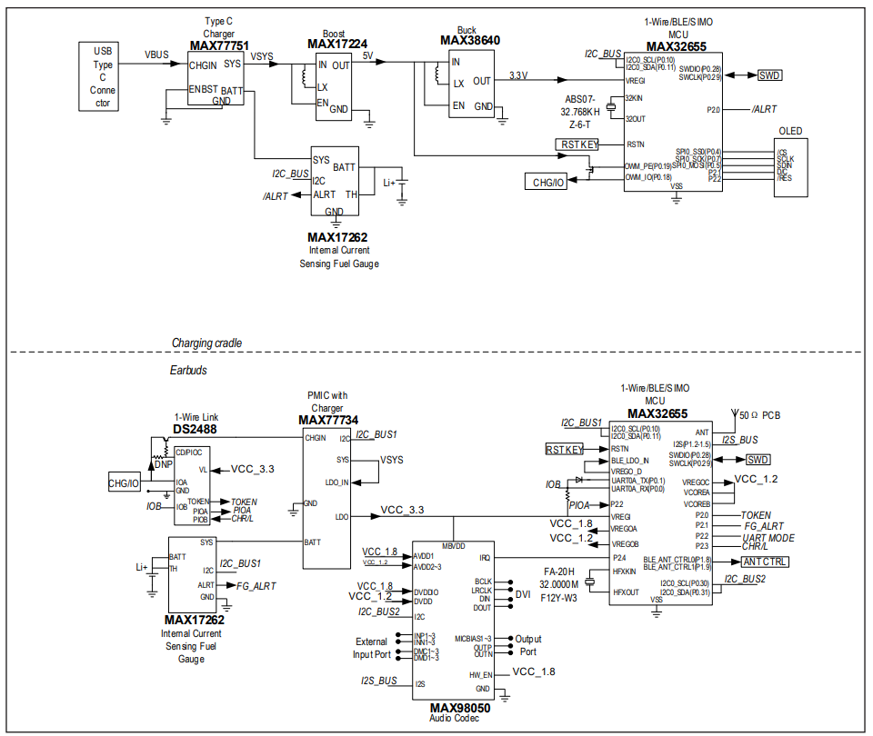
Figure 2 shows the block diagram of the MAXREFDES1302. When the earbuds are connected to the cradle via two touch points, the cradle starts scanning and then sends a hand-shaking signal to the earbuds. If the earbuds are detected, the cradle delivers power to the earbuds to charge the batteries of the earbuds. At the same time, the cradle collects information of the batteries on the earbud side is instantly available and shows their state-of-charge. The cradle also measures its own battery and shows its state-of-charge. The earbuds should be able to play audio when they are outside the cradle. In this case, additional I2S audio inputs and outputs are necessary.
Microcontroller
The MAXREFDES1302 uses the MAX32655 microcontroller on the cradle side and the earbud side. The MAX32655 microcontroller is an advanced system-onchip featuring an Arm Cortex-M4F CPU for efficient computation of complex functions and algorithms. The MAX32655 integrates power regulation and management with a SIMO buck regulator system and supports 1-Wire protocol. The MAX32655 also supports the latest generation Bluetooth 5.2 Low Energy radio, supporting low-energy audio transmission. The MAX32655 can meet the design requirements perfectly due to its smallsize and low-power with large memory space, and it can support 1-Wire interface and BLE. The push buttons SW1 and SW2 can be used to reset the respective microcontroller manually.
Audio Codec
The MAX98050 is a low-power, high-performance audio coder/decoder (CODEC) with integrated low-latency digital filters for the wireless hearables, headsets, and headphones.
The MAX98050 features a mono playback channel with a 5-band biquad equalizer and a high-efficiency, fully differential hybrid class-AB/class-D headphone amplifier. The playback headphone amplifier is optimized for extremely low output noise levels and minimized quiescent power consumption at highest output power efficiency.
The MAX98050 has three microphone input channels, which can support many audio cases. Each channel can individually record from either an external analog or digital microphone, and then can route audio data to both the record channels (to the digital audio interface) and the internal low-latency digital filter channels. A fourth record channel to the digital audio interface is provided to allow the host to monitor the playback channel output digital data.
The MAXREFDES1302 uses the MAX98050 on the earbud board. All of the inputs and outputs of the MAX98050 are reserved, which can help users to test its performance.
Battery Measurement
The MAX77751 and the MAX17262 are used for cradle battery management while the MAX77734 and the MAX17262 are used for earbud battery management.
The MAX77751 is a standalone, 3.15A charger with integrated USB Type-C CC detection and reverse boost capability. The fast-charge current and top-off current thresholds are easily configured with resistors. The MAX77751 operates with an input voltage of 4.5V to 13.7V and has a maximum input current limit of 3A. The IC also implements the adaptive input current limit (AICL) function that regulates the input voltage by reducing the input current, to prevent the voltage of a weak adapter from collapsing or folding back.
The MAX17262 is an ultra-low power fuel-gauge IC which implements the Analog Devices ModelGauge m5 algorithm. The MAX17262 monitors a single cell battery pack with integrated internal current sensing for up to 3.1A pulse current. The IC monitors a single-cell battery pack and supports internal current sensing for up to 3.1A pulse current. The IC provides the best performance for batteries with 100mAhr to 6Ahr capacity. The ModelGauge m5 EZ makes fuel-gauge implementation easy by eliminating battery characterization requirements and simplifying host software interaction. The ModelGauge m5 EZ robust algorithm provides tolerance against battery diversity for the most lithium batteries and applications.
The MAX77734 is a tiny power-management integrated circuit (PMIC) for applications where size and simplicity are critical. The IC integrates a linear-mode Li+ battery charger, low-dropout linear regulator (LDO), analog multiplexer, and dual-channel current sink driver. The charger is designed for small-battery systems that require accurate termination as low as 0.375mA. The circuit can instantly regulate the system voltage when an input source is connected even if the battery is drained.
Power Supply
On the cradle side, the MAX38640 is used to generate a stable 3.3V output from VSYS to power the microcontroller and the OLED module. The MAX17224 is used to generate a stable 5V output from 3.3V, which supplies the charging current for the earbuds via 1-Wire bus. A MOSFET is adopted to control the timing of 1-Wire charge and 1-Wire communication
On the earbud side, the MAX77734 features a 150mA LDO, which provides ripple rejection for the audio and other noise-sensitive applications. It provides the main power for the MAX32655 and the MAX98050. The SIMO of the MAX32655 provides the analog power rail for the MAX98050.
The battery should be small while it needs to supply enough energy for continuous operation of the cradle and earbuds. A 1500mAh 3.7V Li+ battery is selected in a cradle design for maintaining the operation of the cradle and charging batteries of the earbuds. Its charge termination voltage is 4.2V, and the MAX77751 on the cradle side configures its fast-charging current to be 500mA, and its top-off charging current to be 100mA. An 130mAh 3.7V Li+ battery is selected in the earbud design for earbud working consumption. Its maximum charging current is 100mA and its charge termination voltage is 4.2V.
Data Communication
The cradle and earbuds need to shake hands and communicate with each other. On the earbud side, the DS2488 works as a simple bridge device between the cradle and the earbud. The microcontrollers on the cradle side and the earbud side can communicate with the DS2488 via IOA pin and IOB pin, respectively. The microcontrollers write or read the buffer of the DS2488 to realize small message exchange. Which side has the token of the DS2488 can communicate with the DS2488. For example, if the cradle has the token, it can write or read the DS2488 via IOA pin. On the contrary, if the earbud has the token, it can write or read the DS2488 via IOB pin. Which side has the token depends on the state of the earbuds.
When earbuds are in the cradle, and the cradle is closed, the cradle charges the batteries of the earbuds. At this moment, the token is on the earbud side and earbuds can update the information of the batteries into the buffer via IOB pin. Once the cradle is open, the cradle stops charging earbuds and the token is on the cradle side. Thus, the cradle reads the buffer of the DS2488 and show the information of the earbud batteries and the cradle battery on the OLED module or to the serial port. At the same time, the cradle updates its own battery information into the buffer for subsequent application expansions.
When earbuds are not in the cradle, the token is on the earbud side, and earbuds update the information of the batteries into the buffer via IOB pin for the next connection between the cradle and earbuds. At this moment, the cradle cannot detect any DS2488 and only shows its own battery state.
The MAXREFDES1302 firmware includes two parts: the cradle part and the earbud part. Both the two parts consist of the peripheral (e.g., fuel gauge, PMIC, etc.) initialization and configuration steps, and an infinite main loop for 1-Wire control.
Cradle Firmware Part
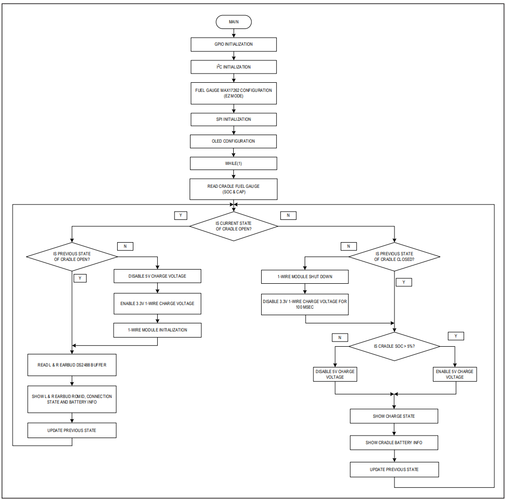
After power-up, the microcontroller on the cradle side initializes GPIOs, configures the fuel gauge, MAX17262, and then configures the OLED module. Then it goes into an infinite loop to poll the state of a GPIO which indicates whether the cradle is open or not. If the cradle is closed, the cradle disables 1-Wire module, enables 5V charge voltage to IOA to charge the earbuds. At this moment, the cradle shows its own battery information on the OLED module or to the serial port. If the cradle is open, the cradle disables 5V charge voltage and enables the 1-Wire module to read or write the buffer of the DS2488. At this moment, the cradle shows its own battery information, together with the earbud battery information read from the buffer on the OLED module or to the serial port.
Figure 3 is the flow chart of the cradle firmware.
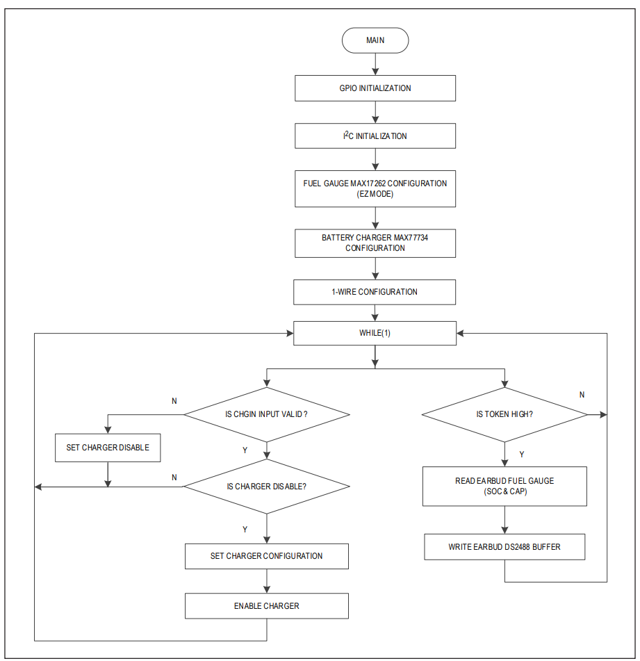
Earbud Firmware Part
After power-up, the microcontroller on the earbud side initializes GPIOs, and configures the fuel gauge, MAX17262, and then configures the charger, MAX77734. Then it goes into an infinite loop to poll the state of the charger whether the input source is debounced or not. If the input source is valid and greater than 4.0V, the charger is enabled and starts the charging process. At this moment, an infinite loop polls the state of a GPIO which indicates whether the TOKEN is HIGH or not. If it is LOW, the cradle gets the communication token. If TOKEN is HIGH, the earbud gets the communication token. When TOKEN is HIGH, the battery information collected from the fuel gauge would be written to the buffer of the DS2488.
Figure 4 is the flow chart of the earbud firmware.
The use of the MAXREFDES1302 is simple. The cradle can work when it is connected to the USB socket, and it can also work when the battery is connected to the board. When the earbuds are connected to the cradle, the cradle automatically communicates with the earbuds, and collects the battery information of the earbuds periodically to show it on the OLED module. When the earbuds are not connected to the cradle, the cradle only shows its own battery information. A serial port monitor can also be used to display the information on communication and charging.
Program Download Interface
The serial wire debug (SWD) interface is used to program the firmware of the earbuds via connectors on the board (J2 for programming the cradle and J7 for programming the earbud). The MAXREFDES1302 uses the MAX32625PICO board as the debug emulator.
文件和资源
-
MAXREFDES1302 Design Files2021/11/23ZIP3 M
-
MAXREFDES1302: Analog Devices 1-Wire True Wireless Stereo (TWS) Cradle and Earbuds2021/11/25PDF783 K
-
通过1-Wire技术简化TWS耳机解决方案2022/4/4 模拟对话
支持与培训
搜索我们的知识库,获取技术问题答案。我们专门的应用工程师团队也会随时为您解答技术问题。