概览
设计资源
设计与集成文件
- Schematic
- Bill of Materials
- Gerber Files
- Assembly Drawings
- Allegro Layout Files
- 3D Print Files
- Software
评估硬件
产品型号带"Z"表示符合RoHS标准。评估此电路需要下列选中的电路板
- EVAL-ADICUP3029 ($60.92) Ultra Low Power Arduino Form Factor Compatible Development Board
- EVAL-CN0503-ARDZ ($541.42) Multichannel Optical-based Liquid Measurement Platform
参考资料
-
EVAL-CN0503-ARDZ User Guide (GitHub)2026/4/16
-
Solutions For Rapid Prototyping: Answering the Needs of Practicing Engineers2023/8/23PDF784 K
-
CN-0503: Multiple Parameter Optical Liquid Measurement Platform (Rev. 0)2020/9/2PDF349 K
-
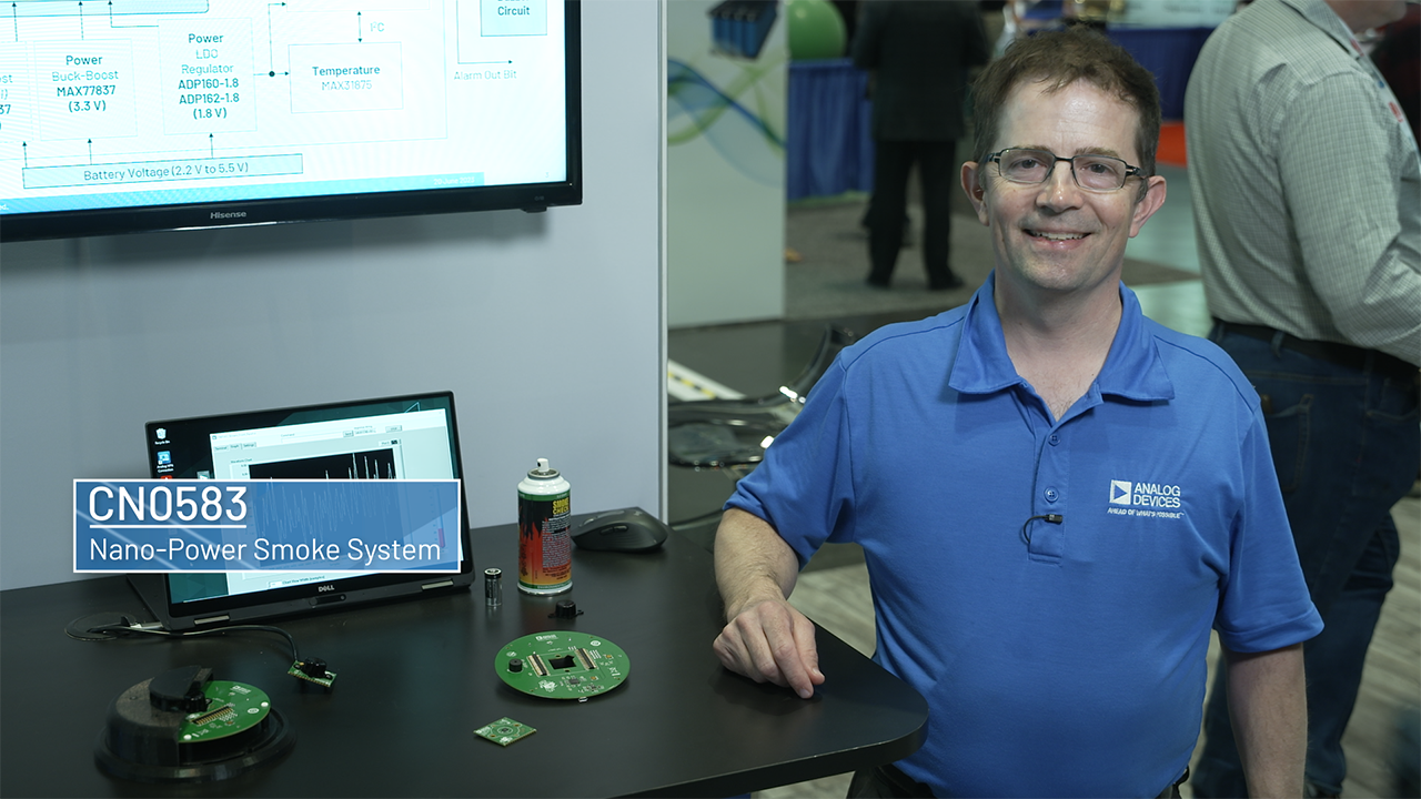 Nanopower Smoke Detection System2025/9/5
 -
 Optical Liquid Analysis in a Flash with ADPD4101 & CN05032024/12/12
 -
 使用ADPD4101快速进行光学液体分析2024/12/12
-
光学液体分析原型制作平台为普遍检测指明了道路2022/1/1 模拟对话
电路功能与优势
Optical techniques are used in a broad class of liquid analysis techniques. Phenomena such as absorbance, fluorescence, scattering, and backscatter are used to detect chemical composition, pH, turbidity, and other chemical and physical properties. Optical techniques have several advantages, namely, they are contact free, not destructive, high precision, and high sensitivity; however, they often require complicated electronics to compensate for electrical and physical errors. Also, defining the optical path and eliminating ambient light interference requires careful enclosure design.
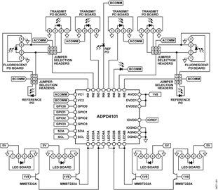
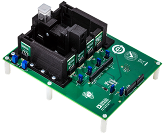
The circuit shown in Figure 1 is a reconfigurable multiparameter optical liquid measurement platform capable of performing colorimetry, turbidity, and fluorometry. The design minimizes complexity by using a highly integrated, multimodal sensor front end capable of simultaneously driving four LEDs, and synchronously measuring four pairs of photodiodes at a flexible sampling rate. Furthermore, the front end has on-chip digital filters and high ambient light rejection that allow the platform to operate with full performance regardless of environmental lighting conditions.
Despite benchtop instrument performance, the system is adaptable to portable and handheld applications. The LED current is configurable to be as low as 2 mA. With a 200 nA standby current and a flexible output data rate, the system achieves ultralow power consumption. Furthermore, the main board is designed in an Arduino-compatible shield form factor for rapid prototyping with common processor platforms.
The platform supports a wide range of LED sources from infrared to ultraviolet wavelengths, and the four independent light paths can be simultaneously measured. Additionally, two of these light paths support perpendicular measurement capabilities for applications like fluorescence and turbidity.
Each light path includes a measurement and reference photodiode that samples the intensity of the incident beam, allowing errors due to LED current source accuracy, LED drift, and mechanical imperfections to be nearly eliminated.

电路描述
Optical Measurement Basics and Theory
Performing optical-based measurements requires various optical, electronic, and optoelectronic devices to convert light-based phenomena into electrical signals that can then be digitized for display or undergo further processing. As shown in Figure 2, an optical measurement system typically includes a fixed or adjustable wavelength monochromatic light source, a means of defining the sample geometry (such as a cuvette or flow through cell), and one or more photodetectors. A means of sampling the incident light intensity may be included to compensate for drift, and interference from ambient light can be reduced by modulating, or chopping, the beam, and synchronously demodulating the detector output.
Advances in semiconductor light sources and detectors allow for compact, low power, optical measurement systems, but precision circuitry is required to drive LEDs, amplify and digitize photodiode current, and calculate meaningful measurement results.
ADPD4101 Multimodal Sensor Front End
The core of the CN-0503 is the ADPD4101 highly integrated multimodal sensor front end. The ADPD4101 integrates all essential LED drive and photodiode signal conditioning circuitry. This device stimulates up to eight LEDs and measures return signals on up to eight separate current inputs. Twelve time slots enable up to 12 measurements per sampling period. Control circuitry includes flexible LED signaling and synchronous detection, rejecting interference from both steady and modulated ambient light (sunlight, LED, fluorescent, and other light sources.) Internal digital filtering allows further reduction in noise due to light contamination, as well as other sources.
With a 400 mA total LED drive capability, 100 dB of dynamic range, and eight inputs and outputs, the ADPD4101 is an ideal solution for high performance laboratory and handheld instruments, including photometric liquid analysis applications.
Sample rate and LED drive current can be fine-tuned to trade power consumption against signal-to-noise ratio (SNR). Power consumption is 30 μW total for LED drive and the ADPD4101 powers at 25 samples per second, appropriate for portable instruments and battery powered Internet of Things (IoT) sensing nodes.
Ambient Light Rejection and SNR Optimization
The ADPD4101 rejects constant ambient light contamination (such as sunlight) by modulating the LED current and synchronously measuring the difference between the excited on state and dark or off state. This ambient light rejection is automatic without the need for external control loops, dc current subtraction, or digital algorithms. The excitation pulse width is programmable down to a minimum width of 1 μs, providing rejection up to 1 MHz from modern solid-state light sources, 50 Hz or 60 Hz from incandescent bulbs, and fluorescent lights with traditional ballasts. Short pulse widths provide the greatest amount of ambient light rejection and the lowest power dissipation, but at the expense of SNR.
The number of pulses used for each sample can be increased to improve the SNR. There is a 3 dB increase for every doubling of the number of pulses. An additional digital integrator chopping can be enabled that inverts the integrator sequence for half of the number of pulses. This chopping eliminates low frequency signals introduced by the integrator and further increases SNR.
There are also multiple modes within the ADPD4101 that can further improve SNR and ambient light rejection under various conditions. See Table 1 for other modes supported by the ADPD4101.
Strong ambient light rejection, coupled with the compensation of imperfections in the optical path, reduces or eliminates the need for shielding and greatly simplifies enclosure design when using the ADPD4101.
Figure 2. Typical Optical Measurement System
| Mode | Description | Purpose |
| Multiple Analog Integration | Pulses LED x number of times before sampling ADC | Sampling very small light intensity responses |
| One-Region Digital Integration | Samples for the dark state are taken before the on state | Sampling light in stable ambient light conditions |
| Two-Region Digital Integration | Half of the samples for the dark state are taken before the on state and the other half of samples are taken after the on state | Sampling light in varying ambient light conditions |
Optical Measurement Path Configurations
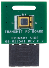
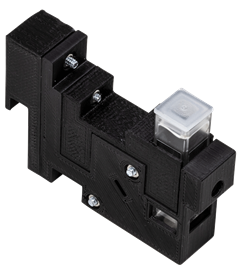
CN-0503 has four configurable optical paths. Each path consists of an excitation LED, condenser lens, beam splitter, reference photodiode, and transmit photodiode. The two outer paths also include perpendicular photodiodes and filter receptacles for fluorescence and scattering measurements. Optionally, a narrowband, band-pass filter and neutral density filter can be added to each path (if required by the application).
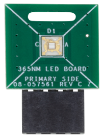
Interchangeable riser boards allow each optical path to be set to various wavelengths. The riser board positions the LED at the focal point of a condenser lens.
The condenser lens focuses the light from the LED into a beam that is directed along the optical path. A band-pass filter can also be added in front of the condenser lens to support the use of wideband LEDs in measurements requiring specific wavelength excitation, such as in absorbance and fluorescence. Additionally, a neutral density filter can be added in front of the condenser lens to uniformly attenuate LED light for applications requiring very low light measurements that are easily saturated by normal LED intensities.
The beam splitter directs a fraction of the incident beam toward a reference photodiode. The reference diode measurement represents the incident light intensity, allowing for compensation of errors due to the current source accuracy of ADPD4101, the LED transfer function, the optical path itself, and the temperature drift.
The transmit photodiode is positioned directly along the optical path and captures light that passes through the sample. In coordination with the reference photodiode, all four optical paths in the system can perform ratio measurements for absorbance and 180° scattering.
In the two outer optical paths, the photodiodes positioned perpendicular from the path capture light emitted and/or scattered by the sample. The combination of photodiodesused for each of the outer optical paths are configurable through selection headers. Additionally, a narrow-band filter can be placed in front of the perpendicular photodiode to further isolate fluorescence from scattered light.

Fluorescence Measurement
Fluorescence is the phenomenon wherein the electrons of certain materials are excited by a beam of light, usually in the ultraviolet range, and almost instantaneously causes them to emit light in another wavelength. The intensity of the emitted light is proportional to the concentration of the material. Using fluorometry to measure the concentration of materials in the solution is often much more sensitive than using absorbance measurements. Furthermore, fluorescence measurements are linear over a wider range of concentrations.
Usually, fluorescence measurements use a detector positioned at 90° from the incident light to minimize its effect in the measurement. Because there are several factors that interfere with the measurement, such as distortions from the light source, external lighting, and slight movements in the sample, a reference detector to measure the incident light is used. Furthermore, a monochromatic or long-pass filter is used with the fluorescent detector to increase the isolation between the incident and the emitted light. Figure 4 shows the optical path for a fluorescence measurement.

CN-0503 is capable of fluorescence measurements using either of the two outer optical paths. For example, to determine the amount of quinine in tonic water, which fluoresces at 450 nm when excited by 365 nm light, a 365 nm LED is installed in one of the two outer optical paths, and a 410 nm long-pass filter is installed in front of the perpendicular photodiode. Fluorescence (and hence, quinine content) is determined by taking the ratio of the perpendicular to transmit measurements.
Absorbance Measurement
Colorimetry uses the light absorbance property of solutes in the liquid solution to determine their concentration based on the Beer-Lambert Law (Equation 1)

where:
c is the molar concentration.
ε is the molar attenuation coefficient.
l is the optical path length.
I0 is the incident light intensity.
I is the transmitted light intensity.
Colorimetry is also used in measurements in which solute concentration is indicated by the color change of a reagent.
Figure 5 shows the optical path configuration for absorbance measurements. The incident beam is directed at a beam splitter that samples the intensity of the beam via a reference photodiode, with the remaining power directed through the sample. The reference measurement allows most of the gain error and drift to be removed in software. Two identical receive paths simultaneously sample the measurement and reference beams, providing rejection of time varying ambient light. Gain mismatch between the receive paths is further reduced by alternately swapping the receive paths and averaging the results.

CN-0503 supports absorbance measurements in all optical paths. These measurements are used in colorimetry that have various applications in water quality analysis. For example, determining the pH of a solution using bromothymol blue as an indicator. Figure 6 shows the various spectral behaviors for the absorbance of bromothymol blue at different pH levels. At two different wavelengths, there is a wide range of possible values for absorbance across pH. This makes it possible to effectively determine the pH of the solution based on the absorbance measurement using a light source at the two specified wavelengths: 430 nm and 615 nm.

Calibration coefficients are determined by measuring the absorbance of buffers of known pH, which are then used to measure the pH of unknown samples.
Turbidity Measurement
Turbidity uses the light scattering property of insoluble materials suspended in the liquid sample. The amount of light scattered by a material, and the scattering angle, differs based on the wavelength of the incident light and particle size. A standard of measurement for turbidity was developed that sets the unit of measurement depending on the geometry, number of detectors, and the wavelength of the light source. Figure 7 shows the optical path for a turbidity measurement using a 90° or 180° detector.

The platform focuses on using the nephelometric turbidity unit (NTU), formazin turbidity unit (FTU), attenuation unit (AU), and formazin attenuation unit (FAU).
| Detector Position | Light Source | |
| Broadband (400 nm to 680 nm) | Infrared (780 nm to 900 nm) | |
| Single 90° | NTU | FTU |
| Single 180° | AU | FAU |
- NTU is measured using a single detector positioned 90° from the incident beam using broadband light with peak spectral output between 400 nm to 680 nm.
- FTU is similar to NTU but conforms to the ISO7027 drinking water quality standard by using a monochromatic infrared light source with peak spectral output between 780 nm to 900 nm.
- AU is similar to NTU but positions the detector at 180° from the incident beam.
- FAU is the ISO7027 equivalent of AU.
The two outer optical paths can be configured for turbidity measurement by using either the transmit and reference photodiode combination or the perpendicular and reference photodiode combination. For ISO7027 compliance, an infrared wavelength LED is used, but a 530 nm LED is adequate for most measurements where ISO7027 compliance is not required.
Software Operations
The ADPD4101 transparently performs many of the required preprocessing operations, such as synchronous detection and averaging, significantly reducing application software overhead. The CN-0503 example firmware provides a set of functions for setting and reading ADPD4101 parameters and arithmetic oper-ations on combinations of readings (ratios, offsets, polynomials), all over a simple serial text protocol. In addition, configurations can be stored to the onboard EEPROM of the CN-0503, allowing the application software to easily return to a known state on power-up.
Results
Figure 8 shows a typical fluorescence measurement. The 365 nm LED is installed in Optical Path 1, and a 450 nm filter is installed in the perpendicular detection path. The system is first calibrated with distilled water, then a sample containing 0.04 ppm quinine is inserted into the cuvette holder.

常见变化
The ADPD4100 is the serial peripheral interface (SPI) variant of the ADPD4101, operating at a maximum serial clock frequency of 24 MHz for applications requiring higher bandwidth or deterministic timing. CN-0409 is a turbidity meter that is essentially a subset of CN-0503, and CN-0363 is a colorimeter application based on discrete analog-to-digital converters (ADCs) and excitation circuitry, controlled by a field-programmable gate array (FPGA) for applications requiring timing or signal conditioning outside the capabilities of the ADPD4101.
电路评估与测试
The CN-0503 includes an Arduino shield interface making it possible to use other compatible development boards for evaluation and prototyping. The firmware and demonstration software use the EVAL-ADICUP3029 controller board to showcase different measurements that can be performed using the system.
Equipment Needed
- PC, Mac, or Linux host with a USB port
- Serial terminal program (PuTTY, TeraTerm, and so forth)
- 1 EVAL-CN0503-ARDZ circuit evaluation board kit
- 1 EVAL-ADICUP3029 development board
- CN-0503.hex software file
Getting Started
This section discusses the general procedure to setup the four optical paths of the CN-0503 to demonstrate the three different types of measurements. For detailed instruction to assemble the mechanical components and setup the board, consult the EVAL-CN0503-ARDZ Hardware User Guide.
For detailed descriptions on the firmware and software flow, functions, and Python examples, consult the EVAL-CN0503 Software User Guide.
- Set the jumper selection headers for the photodiodes in Optical Path 1 and Optical Path 4 to use the perpendicular and the reference photodiodes.
- Set all LEDs and input/output (I/O) references to use power and I/O voltages from the Arduino controller.
- Enable the connection to the 1.8 V low dropout regulator (LDO).
- Assemble the EVAL-CN0503-ARDZ system according to the instructions shown in the EVAL-CN0503-ARDZ Hardware User Guide.
- Figure 9 shows a completed setup for the EVAL-CN0503-ARDZ with cuvette holder positioned in Optical Path 4.
- Connect the EVAL-ADICUP3029 to the bottom of EVAL-CN0503-ARDZ using the Arduino connectors
- Connect to the EVAL-ADICUP3029 to the host PC via a USB micro cable.
- Download the CN-0503 demo firmware to the EVAL-ADICUP3029 by copying the prebuilt hex file directly into the DAPLINK drive (see the ADICUP3029 User Guide).
- Open a serial terminal and connect to the ADICUP3029 COM port. A default configuration profile automatically loads.
- Enter the commands, MODE CODE, then STREAM 5 to take five readings for each of the transmit and reference paths, reporting results in ADC counts. Typical response is shown in Figure 10.
- Enter the commands, MODE ARAT, then STREAM 5, to take five readings in absolute ratio mode (ratio of the transmit reading to reference reading). Figure 11 shows a typical output when a neutral sample is inserted in Optical Path 1 and all other paths are left empty.
- With the basic operation established, the platform can be configured to perform the additional measurements described in the EVAL-CN0503-ARDZ Hardware User Guide.