Voltage balancing techniques for series super capacitor connection for MAX38886/8/9
Abstract
For applications where the supercapacitor needs to be charged to more than 2.5V or 2.7V, engineers are forced to connect multiple supercapacitors in series as the standard supercapacitor voltage is rated to 2.7V and they are of lower cost. This application note reviews the voltage balancing techniques in series supercapacitor connections for the MAX38886/MAX38888/MAX38889 backup regulators.
Introduction
The use of supercapacitors is rapidly increasing in energy storage applications such as handheld industrial equipment, portable devices with removable batteries, industrial sensors and actuators, etc. When such applications require more voltage than the normal 2.7V on supercapacitors, the option is to stack multiple supercapacitors in series. But due to capacitance tolerances, different leakage currents and ESR, the voltage across each capacitor is not distributed equally. This leads in voltage imbalance across supercapacitors since one supercapacitor voltage will have greater voltage than the other supercapacitor. As the temperature and age of supercapacitors increase, this voltage imbalance become worst and the voltage across one supercapacitor may increase to more than the rated voltage. It is very important to keep the voltages balanced across each supercapacitor to ensure long operational life.
MAX38886/MAX38888/MAX38889 4A/2A Reversible Buck-Boost Regulators for Backup Power Applications
The MAX38886/MAX38888/MAX38889 are storage capacitors or capacitor bank backup regulators designed to efficiently transfer power between a storage element and a system supply rail in reversible buck and boost operations using the same inductor. When the main supply is present and above the minimum system supply voltage, the regulator operates in buck mode and charges the storage element at programmed peak inductor currents. When the main supply is removed, the regulator operates in boost mode and prevents the system from dropping below the minimum operating voltage, discharging the storage element at a programmed peak inductor current.
For this study, we are considering the following test case.
System maximum voltage during normal operation, VSYS = 5V.
System minimum voltage while back-up operation, VSYS_MIN = 4.75V.
Supercapacitor maximum voltage while charging operation, VSC_MAX = 4.5V.
Series Connection of Supercapacitors for MAX38886/MAX38888/MAX38889
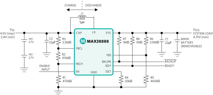
For this application, the supercapacitor must be charged to 4.5V, and during the backup, the supercapacitor voltage is boosted and regulated to 4.75V when the actual system voltage is absent. The application circuit for this condition is depicted in Figure 1.

Figure 1. Application circuit of MAX38888.
In the Figure 1 application circuit, the supercapacitors are rated to 2.7V, which is the standard rated voltage of supercapacitors. So, we have used two 11F supercapacitors in series to increase the voltage rating. Once the charging mode starts and the supercapacitor charges to 4.5V, the voltage across each capacitor is measured as in Table 1.
|
VSYS (V) |
VCAP_TOTAL (V) |
VCAP_TOP (V) |
VCAP_BOTTOM (V) |
Voltage Difference (mV) |
| 5.0 |
4.43 |
2.17 |
2.26 | 97.00 |
Table 1 shows that the voltage difference between the top and bottom supercapacitors is ~97mV and this reading has been taken at +25°C ambient temperature. The leakage current, capacitance, and ESR changes with temperature and age. For example, the supercapacitor used in this application circuit has a leakage current of 6µA at +25°C ambient temperature and the leakage current increases to ~300% at +65°C temperature. These changes in the parameters of the supercapacitors may sometimes lead to an increase in voltage imbalance and one capacitor may also see a voltage greater than the rated voltage. This may also damage the supercapacitor or quickly degrade the life of the supercapacitor in the long run.
There are a few methods which can be used to keep the voltages balanced across each capacitor by adding additional components. The following are a few methods that help to keep the voltages across the supercapacitor balanced.
Methods of Voltage Balancing
- Voltage balancing with balance resistors/passive method.
- Voltage balancing using an op amp circuit.
- Voltage balancing using the SAB auto-balancing MOSFET arrays/active method.
1. Voltage balancing with balance resistors/passive method
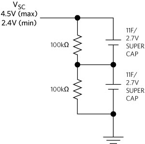
The simple and most cost-effective way to balance the voltages across the supercapacitors is to connect resistors of equal value across each supercapacitor. As the resistor is connected permanently across supercapacitors, the power dissipation in the resistors will be continuous. The balancing resistors across the supercapacitor connection are shown in Figure 2.

Figure 2. Voltage balancing using balancing resistors.
When 100k? resistors are used across each supercapacitor, the voltages across each supercapacitor is measured as in Table 2.
| VSYS |
VCAP_TOTAL (V) |
VCAP_TOP (V) |
VCAP_BOTTOM |
Voltage Difference (mV) |
| 5.00 |
4.40 |
2.18 |
2.22 |
44.00 |
There are a few disadvantages using this method. The resistor value must be selected such that it provides significant current draw to achieve acceptable balance in the voltages. At the same time, a smaller value for resistors causes larger power consumption from the supercapacitor. As the supercapacitor temperature and age increases, the leakage current also increases which makes the circuit less and less effective with time. If the selected resistor values are very high, it takes a long time to balance the supercapacitor voltages.
2. Voltage balancing using an op-amp circuit
The above additional circuit using balancing resistors has a continuous power dissipation and is lossy. To reduce power dissipation and to maintain balance in the voltages, the balance circuit can be implemented using an operational amplifier. This solution can contribute faster voltage balance even if high resistance values are used as the ladder network.
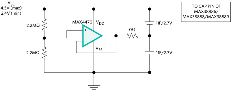
To reduce the power loss in the additional circuit, choose an op amp which consumes a lot less power like the MAX4470 which needs an ultra-low supply current of at least 750nA. The operating voltage of the op amp should be higher than the maximum supercapacitor voltage. A damping resistor may be needed to avoid abnormal oscillation.

Figure 3. Voltage balancing using an op amp circuit.
The balance circuit in Figure 3 will be active when the voltage across the supercapacitor is not balanced. Once the voltages across each supercapacitor are balanced, this circuit consumes less power. Hence, this circuit is a highly energy-efficient method. We are using 2 x 2.2M? resistors across the supercapacitor to ground and the IC consumes a lot less supply current. The total power consumption is significantly less than the earlier passive method.
The voltage across each capacitor using the op-amp method is measured as in Table 3.
| VSYS |
VCAP_TOTAL (V) |
VCAP_TOP (V) |
VCAP_BOTTOM (V) |
Voltage Difference (mV) |
| 5.00 |
4.33 |
2.17 |
2.16 |
3.50 |
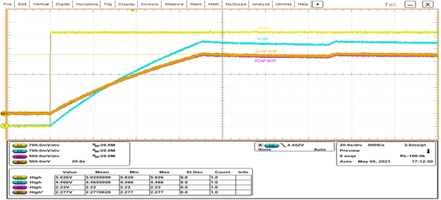
The waveforms in Figure 4 show the startup behavior while the supercapacitors are charging and the op amp circuit is used for voltage balancing. The waveform shows the VSYS (yellow), VCAP_TOTAL (blue), VCAP_TOP (orange), VCAP_BOTTOM (pink).

Figure 4. Startup waveform during supercapacitor charging using an op amp balancing circuit.
3. Dedicated IC-based balancing circuit
There are few dedicated IC-based supercapacitor auto-balancing MOSFET arrays that can serve as active balancing circuits for supercapacitors. These MOSFET arrays offer self-balancing of stacked series-connected supercapacitors while dissipating near zero leakage currents, practically eliminating extra power consumption. The series-connected stack is continuously monitored and automatically controls balancing of its voltage and leakage current.
This is a special type of MOSFET that has a very tight gate threshold voltage specification. The set supercapacitor voltage should be twice that of the threshold voltage. Each capacitor will charge to the gate threshold voltage. But this will be an expensive method of voltage balancing as the cost of these dedicated ICs is more.
Comparison Between Passive, Active Methods of Voltage Balancing
Table 4 shows the overall comparison of each type of voltage balancing technique discussed.
| Parameter | Resistor Circuit | Op-Amp Circuit | Dedicated IC |
| Circuit cost | Low | Medium | High |
| Voltage balance performance | Medium | Good | Good |
| Power consumption | High | Less | Less |
| Operating voltage unit | No limit | Limited | Limited |
| Component count | 2 | 4 | 1 |
| Implementation | Easy | Moderate | Easy |
Conclusion
This application note discussed why voltage balancing is required in series supercapacitor connections and reviewed different voltage balancing techniques for series super capacitor connections. The performance of each technique was compared.