Thermal Switches Provide Circuit Disconnect
Abstract
A pair of temperature switches control a thermal disconnect circuit for system temperature protection. The circuit "crowbars" the power supply when excessive temperature is detected by the thermal switches.
A temperature sensor can provide an interrupt to a microcontroller when the measured temperature goes out of range. The microcontroller implements the proper protective action when one of the temperature monitors detects an over temperature condition. But sometimes it is easier and more cost effective to simply disconnect the offending circuit from the power supply without getting a microcontroller involved.
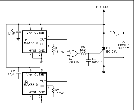
Multiple temperature sensors are needed when more than one hot spot needs to be monitored. A simple thermal-protection circuit (Figure 1) includes two temperature switches (U1 and U2) with active-high outputs. Temperature thresholds for these switches are set by resistors R1 and R2, and the switch outputs connect to the inputs of a dual-input OR gate (U3). OR gates with more than two inputs are available if more than two temperature switches are needed. When excessive temperature drives either input high, the OR-gate output is driven high, causing a silicon controlled rectifier (SCR) to crowbar the power supply and blow the fuse.

Figure 1. This thermal-protection circuit includes a crowbar device (D1) driven by thermal switches U1 and U2.
Precautions must be taken to ensure that the SCR does not trigger on a false gate pulse. Power supply transients can cause a false high signal at the output of the OR gate and cause the SCR to turn on. Once triggered, the SCR is not able to turn off, and the fuse will blow. A small RC filter (R3 and C3) suppresses any gate transients that would otherwise turn on the SCR.