Design Note 1017: LTC4099 Provides Unprecedented Control of USB Power Management and Battery Charger Functions Using I2C
Introduction
The LTC4099 high efficiency USB power manager and Li-Ion/Polymer battery charger seamlessly manages power distribution from multiple sources in portable applications. It is differentiated from other USB power managers by its bidirectional I2C port that allows the host microprocessor to control and monitor all aspects of the USB power management and battery charging processes. In addition, a programmable interrupt generation function alerts the host microprocessor to changes in device status and provides unprecedented control of power management functions. This high degree of configurability allows post-layout changes in operation, even changes in the field, and it allows a single qualified device to be used in a variety of products, thus reducing design time and easing inventory management.
Many Desirable Features in a Small Package
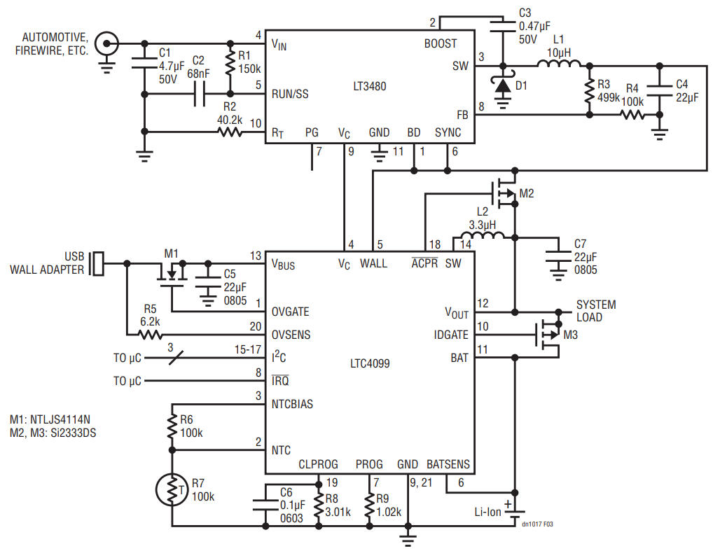
In addition to all of its power management functions, the LTC4099 includes overvoltage protection, auxiliary regulator control (to manage high voltage inputs), and an overtemperature battery conditioner (see Figure 3). All of these features are housed in a tiny 20-lead ultrathin (3mm × 5mm × 0.55mm) plastic QFN package.
Overvoltage protection is implemented via an internal MOSFET controller that shuts off an external MOSFET if the part detects excessive voltage. Although this feature is usually used to protect the USB input, it can protect any port. The standoff voltage is determined by the external MOSFET. This is very useful for environments subject to voltage transients that could damage downstream devices, allowing them to be disconnected during the voltage transients.
The LTC4099 uses the Bat-Track™ adaptive output control function to create a high efficiency battery charger. With the Bat-Track feature, the output, VOUT, of the switching regulator is kept approximately 300mV above the battery voltage. This not only allows the battery charger to operate very efficiently, but it increases the current available for battery charging. This is because the VOUT switching regulator behaves like a transformer, exchanging output voltage for output current.
The LTC4099 extends the usual Bat-Track feature with auxiliary regulator control. Auxiliary regulator control detects the presence of an external high voltage (HV) buck regulator, shuts off power from the USB and draws it only from the HV buck. In addition, the Bat-Track feature is applied to the HV buck regulator by controlling the external regulator’s output to within approximately 300mV of the battery voltage. Auxiliary regulator control thus retains excellent efficiency and minimizes charger dissipation even while using an HV buck regulator to charge the battery.
The auxiliary regulator control is implemented using the WALL, ACPR and VC pins. The WALL input detects the presence of voltage from an external HV Buck regulator, and activates the ACPR signal and VC signals. When the WALL pin detects a voltage greater than 4.5V, ACPR asserts low, turning the P-channel MOSFET on, and connecting the output of the HV buck regulator to VOUT. The LTC4099 then controls the VC pin of the HV buck regulator to ensure that the Bat-Track feature is preserved.
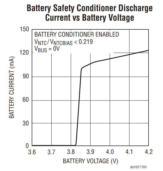
Li-Ion/Polymer batteries have a reduced useful lifetime when stored at high temperature with full charge voltage. The battery conditioner circuitry within the LTC4099 protects the battery from damage by discharging some of its energy when it reaches a certain temperature as measured by a thermistor. This reduces the battery voltage to a safe level as shown in Figure 1. For example, this would protect a device with a fully charged battery that is left on the dashboard of a car. The battery conditioner can be enabled or disabled (default) via the I2C channel.

Figure 1. The Battery Conditioner Protects the Battery by Releasing Energy to Lower the Battery Voltage when the Battery Is Hot. The Battery Conditioner Discharge Current Varies with Battery Voltage, as Shown Here.
The thermistor measurement circuit uses a sampling technique for ultralow power consumption, so that the battery conditioner function can be enabled without adding appreciably to the battery discharge current.
Parameters Configurable Via the I2C Port
The USB power management function of the LTC4099 controls the load presented to the USB power connection. The CLPROG resistor controls the magnitude of the average input current. This is done by impressing a fraction of the average USB load current on the CLPROG resistor and using this voltage as feedback to control the input current. However, the LTC4099 provides a new level of control by allowing this current limit to be set to one of eight different levels via the I2C port. The ratio of these eight levels is fixed internally, but the magnitude is scaled by the CLPROG resistor. This high degree of programmability allows the LTC4099 to support a variety of USB connections without any hardware changes. Products using the LTC4099 may thus behave very differently when connected to a wall adapter or a USB On-The-Go device. For example, the device may be programmed to charge and operate when powered from a wall adapter, but only charge during a sleep state if powered from a USB On-The-Go device.
The Li-Ion/Polymer battery charger is also completely configurable via the I2C port. The battery charger can be turned on/off, the float voltage can be set to 4.1V (default) or 4.2V, plus the charge current, the end-of-charge detection threshold and the battery safety timeout interval can be programmed.
The PROG resistor controls the charging current, as well as the end-of-charge detection threshold. For a given PROG resistor the charge current can be set to one of eight (8) different levels. The charge current level can be set via the appropriate bits in the I2C channel. This gives the system designer a great deal of flexibility to add useful features. For example, a product could have a standard capacity battery and a premium high capacity battery and still maintain the same recharge times. Alternatively, the system could fast charge the battery for a specified amount of time and then reduce the charge current to maintain battery life.
Once the battery voltage reaches the programmed float voltage of 4.1V (default) or 4.2V, the battery charger transitions to constant voltage mode. The battery charger will remain in constant voltage mode until the safety timer times out. The safety timer interval can be programmed from one to eight hours, in one-hour increments, and defaults to four hours. The safety timer ensures that the risk of a battery problem is automatically minimized. In constant voltage mode, the battery charging current should taper off, asymptotically, to zero. The C/x threshold is the charge current, in constant voltage mode, below which charging can be considered to be done. In the LTC4099 the C/x threshold can be programmed via the I2C channel from among four different levels.
Gather Status Information Over the I2C Channel
The LTC4099 I2C channel implementation is bidirectional, allowing the readback of a status byte. This status byte will report the status of the USB input voltage, HV Buck input, whether or not the LTC4099 has determined the attached Li-Ion battery is defective, whether or not the LTC4099 is in thermal regulation, whether or not the battery is at an acceptable temperature for charging as reported by the thermistor, and the charger state. The last two statuses are two bits wide and can each report 4 states. The temperature status can report “no NTC fault,” “battery too cold,” “battery too hot,” and “battery overtemp.” The charger status can report “charger off,” “constant current mode,” “constant voltage mode—IBAT greater than the threshold C/threshold” and “constant voltage mode—IBAT less that the C/threshold.” This status readback allows a comprehensive polled monitoring of both the USB power management and Li-Ion/Polymer battery charging processes. Polled monitoring may be preferred in computationally challenged environments to avoid the overhead of the Interrupt Service Routine (ISR) context switching. All the events monitored by the LTC4099 occur slowly, and thus probably do not need a real time response.
Configure Interrupt Masking Via the I2C Port
The LTC4099 supports a complete set of maskable interrupts for environments that place a priority on certain events. Even in environments where polling would be preferable for general operation, there may be operating conditions where interrupt-driven operation is very useful. For example, in an MP3 player that is off and charging, an interrupt signal that charging is done could wake up the host microprocessor, allowing the player to chime, indicating battery charge completion to the user.
The interrupt generator can be programmed to assert an interrupt when any of the status bits change. This could be a change from USB voltage present to not present. Or, it could be the change from the battery charger being in constant current mode to constant voltage mode. The interrupt generator does not look for a bit being high or low, but rather for a bit changing states. An interrupt remains asserted until cleared and, no further interrupts are captured until the current pending interrupt is cleared. If the LTC4099 is read with an I2C ACK (acknowledge) by the host microprocessor, any current pending interrupts are cleared (see Figure 2). If another interrupt event occurs, the interrupt is immediately reasserted.

Figure 2. An I2C Read with ACK to Clear an IRQ Fault Interrupt.
The interrupt mask register thus allows a great deal of flexibility for system implementation. It allows the system designer to disallow certain interrupts while allowing others, still only consuming one ISR vector.
Conclusion
The LTC4099 not only integrates many useful USB power management and Li-Ion/Polymer battery charger features, but couples them to a bidirectional I2C interface. This offers a very high degree of flexibility and versatility, and allows a single device to be used for a variety of products, reducing design time, time to market and inventory costs. It also allows implementation of features highly valued by end users, such as field upgradeability and customization.

Figure 3. A single IC, the LTC4099, Efficiently Manages Power from Three Sources: the USB, a Li-Ion Battery and a Stepped-Down High Voltage Source. Its Efficient Battery Charger Uses the Bat-Track Feature to Minimize Power Losses When Charging the Battery.
