Design Note 455: Low Profile Synchronous, 2-Phase Boost Converter Produces 200W with 98% Efficiency
Introduction
Automotive audio amplifiers require a high power boost converter that is both efficient and compact. High efficiency is essential to keep dissipated heat low and avoid bulky and expensive heat sinks. The LT3782A is a 2- phase synchronous PWM controller, making it possible to produce a low profile, high power boost supply that achieves 98% efficiency.
A 24V Output Boost Converter at 8.5A (Continuous), 10.5A (Peak) from a Car Battery
Figure 1 shows a boost converter that generates 24V from an input voltage range of 8.5V to 18V. Output power is 200W continuous and 250W for short pulse loads, corresponding to 8.5A continuous current and 10.5A pulsed current.

Figure 1. Synchronous Boost Converter Based on the LT3782A (VOUT = 24V at 8.5A, VIN = 8.5V to 18V).
This circuit comprises three major sections. Two are the phase-interleaved power trains, and the third is the control circuit.
Each power train includes an inductor, two switching MOSFETs, a synchronous MOSFET and an output capacitive filter. The output filters are connected together in parallel. Schottky diodes D1 and D2 increase efficiency during the dead time.
The control circuitry can be further divided into three parts: the PWM functionality based on the LTC3782A (U1) and two high side drivers around the LTC4440- 5 (U2 and U3). A linear pre regulator based on Q7 generates the required bias voltage for U2 and U3. This approach allows the use of logic-level MOSFETs to minimize gate losses.
The centerpiece of the control circuit is the LT3782A. This 2-phase PWM controller features low side gate signals and corresponding synchronous signals for high side gate control. Control signals are interleaved by running the two stages 180° out-of-phase. The 2-phase approach with accurate channel-to-channel current sharing minimizes electrical and thermal stress on power train components, and reduces EMI. Using the LTC4440-5 as a high side driver allows for high frequency switching.
Performance Results
This converter aims for high efficiency and low profile, and it succeeds in reaching both goals with efficiency reaching 98% (Figure 2) and a maximum component height of 10.5mm. Output voltage regulation over the full input voltage and output current ranges is better than 2%. Figure 3 shows the transient response with a 3A step load.

Figure 2. Efficiency vs IOUT (from Circuit in Figure 1).

Figure 3. Transient Response of the Circuit in Figure 1 for a 3A Loadstep.
Basic Calculations and Component Selection
This section shows how to make a preliminary selection of inductors and MOSFETs. Detailed calculations of the losses and converter efficiency evaluation can be found in Robert W. Erickson’s Fundamentals of Power Electronics, 2nd edition.
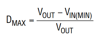
For CCM operation, the maximum duty cycle at low line can be found from the following expression:

Average inductor current and peak current can be calculated as follows:

The peak current through the switching MOSFET is equal to IL(PEAK), and the RMS value of the MOSFET current is:

The peak current through the synchronous MOSFET is equal to IL(PEAK), and the RMS MOSFET current value is:

The MOSFETs should be rated to handle the output voltage plus 20% to 30% of headroom.
Conclusion
The LT3782A based 2-phase synchronous boost converter provides high efficiency, excellent transient response and excellent line and load regulation over a wide input voltage range. High power, high efficiency and a low component profile allow this converter to fi t into tight spaces commonly found in automotive environments.
