AN-1093: Synchronization of Multiple AD9122 TxDAC+ Converters
Introduction
The AD9122 is a dual 16-bit, high dynamic range, digital-to-analog converter (DAC) that provides a sample rate of 1230 MSPS. In some applications, such as those requiring beam steering, the user needs to synchronize multiple DACs in the system. The AD9122 features multichip synchronization, where DAC outputs from multiple AD9122 devices can be synchronized within a DAC clock cycle. There are two synchronization modes in the AD9122. This application note describes the differences between the two modes and when and how to use the multichip synchronization function in the AD9122. The content in this application note also applies to synchronization of multiple AD9125 and AD9148 TxDAC+® converters.
Sources of Variation
A DAC introduces a variation of pipeline latency to a system. The latency variation causes the DAC output from different DAC devices to not be aligned and the skew to vary from power-on to power-on. In applications where fixed latency is desired, the variation must be removed. Fixed latency in this application note is defined as fixed time delay from the digital input to the analog output in a DAC from power-on to power-on. It assumes the same clocking conditions, that is, same data clock input (DCI), frame clock, DAC clock, and sync clock. With fixed latency, synchronization of multiple DACs is achieved.
There are two areas in the AD9122 where the latency can vary, the FIFO and the interpolation filters. The FIFO introduces a latency variation up to one data clock period. The interpolation filters add a variation up to:

Therefore, the maximum latency variation without turning on the synchronization in the AD9122 is:

For example, given the data clock rate fDATA = 300 MHz, 4× interpolation in a system, the maximum latency variation, or the maximum skew between DAC outputs from multiple AD9122 devices, is (2 − ¼) × 3.3 ns = 5.8 ns.
Based on this calculation, the first question to ask in the design is whether synchronization of the DACs is needed. Because extra system design efforts together with turning on the synchronization state machine in the AD9122 is required to make DACs synchronized, synchronization adds complexity to the system design (described in detail in the System Design Considerations for Synchronization section). It is highly recommended that the user define the synchronization requirements and assign a timing budget for the DACs before determining whether synchronization needs to be implemented. If the maximum DAC latency variation is within the budget, synchronization does not need to be implemented. Otherwise, the synchronization state machine needs to be turned on to reduce the latency variation.
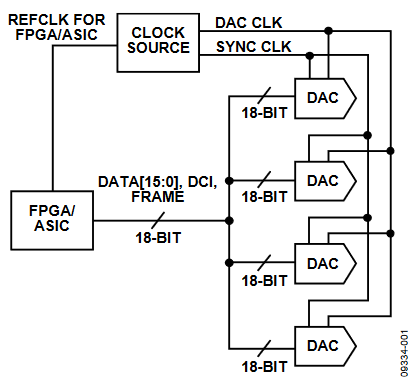
Figure 1. Block Diagram of Synchronizing Multiple AD9122 TxDAC+ Converters.
Theory of FIFO Operation
The FIFO in the AD9122 is a multi-data-slot buffer that helps to hand off the data from the DCI clock domain to the DAC clock domain. In the AD9122, there are eight dual-word (8 × 32-bit) slots in the FIFO. Each slot stores a pair of I and Q data. There are two pointers for the input and output data of the FIFO, the FIFO write pointer and the FIFO read pointer. The two pointers circulate the FIFO from Slot 0 to Slot 7 and back to Slot 0. They indicate, at a particular time, which FIFO slot the input data is going into and which FIFO slot the output data is coming out of. This operation is analogous to the operation of a water reservoir.
A reservoir holds a certain amount of water and has incoming and outgoing water. To keep a constant water level in the reservoir, the speed of the incoming water must be the same as that of the outgoing water. It is fine if the two speeds fluctuate a little because the reservoir absorbs the difference between them, accumulating up to half of its volume. As long as the volume of the incoming and outgoing water is the same on average, the reservoir is never empty or overflowing.
In the AD9122, the empty or overflowing status of the FIFO is reached when the read pointer and write pointer point to the same FIFO slot. At this time, the data transfer in the FIFO is corrupted and thus the DAC output is incorrect. When the FIFO operates normally, the input data goes into the FIFO at the data rate, and the output data goes out of the FIFO at the same rate on average. The FIFO write pointer is controlled by an internal clock derived from the DCI clock. The FIFO read pointer is controlled by an internal clock derived (divided down) from the DAC clock. The action of FIFO reset snaps these two pointers apart and the offset between them is determined by the FIFO phase offset (Register 0x17). Typically its value is 4 for maximizing the capacity of absorbing the rate fluctuation between the read and write side.
Data Rate Mode vs. FIFO Rate Mode
The major difference between the data rate mode and the FIFO rate mode is the way the FIFO is reset. In the data rate mode, the write pointer of the FIFO is reset when the read pointer goes to Slot 0. Upon a triggering event (see the FIFO Resetting Methods section for details on triggering events), the write pointer is not reset until the read pointer goes to Slot 0.
If the FIFO phase offset is set to 4, the write pointer is reset to Slot 4 when FIFO reset happens in the data rate mode. Because of this FIFO reset mechanism, the phase relation between the DCI and DAC clock is uncritical as long as the FIFO is not reset constantly. Regardless of the phase relation between these two clocks upon system power-on, the FIFO reset in the data rate mode ensures that the read and write pointers are always about four (can be three, four, or five) FIFO slots apart. During the operation, the DAC requires the phase between the DCI and DAC clock to be locked. Unlocked phase translates to a situation in which the read and write pointers randomly skip around in the FIFO and thus corrupt the transmit data. The normal FIFO operation requires the pointers to run in an order from Slot 0 to Slot 7 and back to Slot 0.
In the FIFO rate mode, the write side of the FIFO is reset to Slot 4 (when Register 0x17 is set to 4) immediately after the trigger. The part does not care where the read pointer is when resetting the write pointer. The read pointer can be at Slot 0, Slot 1, or any possible FIFO slot. Therefore, the phase offset between the read and write pointer is arbitrary upon each FIFO reset.
As previously mentioned, the optimal FIFO setting is for the phase offset between the two pointers to equal half of the FIFO depth, which is 4 in the AD9122. To achieve this optimal level, in the FIFO rate mode, the user must manually add an extra offset in Register 0x17 if the offset after the FIFO reset is not optimal. For example, upon power-on, Register 0x17 is set to 4. After the FIFO reset, the FIFO thermometer readback (Register 0x19) is 0x03, which means the offset between the pointers is 2. It is two slots away from the optimal setting. To obtain the optimal setting, the user must change the value of Register 0x17 to 6, which is the original value plus 2. The FIFO thermometer readback should be 0xF after the adjustment.
FIFO Resetting Methods
There are two FIFO resetting methods (triggers). The first is through SPI commands. The user can write 0x02 to Register 0x18 for a FIFO reset, and verify its completeness by reading back the value in the same register. When the reset is complete, the read-back value is 0x07. The second way to reset the FIFO is using the frame signal. The period and the positive pulse length of the frame signal must meet the requirements listed in Table 1 to be deemed a FIFO reset trigger.
| Synchronization Mode | Frame Clock Maximum Rate | Positive Pulse Length |
| FIFO Rate Mode | fDATA/8 | ≥ 1/fDATA |
| Data Rate Mode | fDATA/2 | ≥ 1/fDATA |
The requirements in Table 1 apply to word mode. The pulse length should be doubled in byte mode and quadrupled in nibble mode. The first FIFO resetting method is called software reset and the second method is called hardware reset because the first one does not require external hardware to generate a frame signal. In the software reset, the FIFO resets once only when the part receives a valid SPI command. In the hardware reset, the FIFO is reset every time a valid frame pulse is received.
A caveat of the hardware reset is that it poses a timing requirement between the DCI and DAC clock in the data rate mode if the frame signal is a periodic signal. When the DAC clock happens to be inside of the setup and hold time window of the DCI, the FIFO can be reset into either the predefined phase offset or the predefined offset ± 1. This ambiguity causes the DAC to lose data points and thus corrupts the DAC output. The user needs to make sure that the DCI and DAC clock meets the timing requirements specified in the AD9122 data sheet in this circumstance. Note that the FIFO rate mode does not have this timing constraint when the FIFO is reset periodically. This timing constraint only exists in the data rate mode with periodic hardware reset of the FIFO.
Recommended Operation Mode For Applications With Synchronization Off
The recommended mode for applications that do not require synchronization is the data rate mode + one-time software FIFO reset. This operation mode is the most straightforward way to set the FIFO into the optimal setting, and it poses no timing constraint on the DCI and DAC clock. To prevent the FIFO from accidentally resetting due to noise, it is required that the frame input be set to Logic 0, that is, FrameP to 0 and FrameN to 1 in the word interface mode. Figure 2 is the recommended SPI command sequence when synchronization is off in the AD9122.
Synchronization Scheme
Based on the calculation from the Sources of Variation section, if a smaller variation is required, the AD9122 provides a synchronization scheme that achieves synchronization accuracy of one DAC clock cycle. The scheme requires the user to generate two external clocks, frame and sync clock. Depending on the synchronization mode, there are timing requirements between the clocks that must be met. These two clocks help remove the two types of the variation in the AD9122, described in the Sources of Variation section.
The sync clock serves as a reference clock in the system to align the internal clocks in multiple AD9122 devices and to remove the variation in the interpolation filters. To serve this purpose, the sync clock has to run at the same speed as or slower than the slowest clock in the AD9122. In the data rate synchronization mode, the sync clock rate (fSYNC) should be at data rate (fDATA) or slower by a factor of 2n, n being an integer. In the FIFO rate synchronization mode, fSYNC should be at 1/8 × fDATA or slower by a factor of 2n, n being an integer. The maximum rate of the sync clock is shown in Table 2. Note that there is a limit on how slow the sync clock can be due to the ac coupling nature of the sync clock receiver. An appropriate value of the ac coupling capacitors should be chosen to ensure the signal swing meets the data sheet specification. The following is an example of the maximum speed of fSYNC. Given fDATA = 200 MHz, the maximum sync clock rate is 25 MHz in the FIFO rate mode or 200 MHz in the data rate mode.
| Synchronization Mode | Sync Clock Maximum Speed |
| FIFO Rate Mode | fDATA/8 |
| Data Rate Mode | fDATA |
The frame clock helps to remove the variation caused by the FIFO. The FIFO is reset by the frame clock as stated in the FIFO Resetting Methods section.
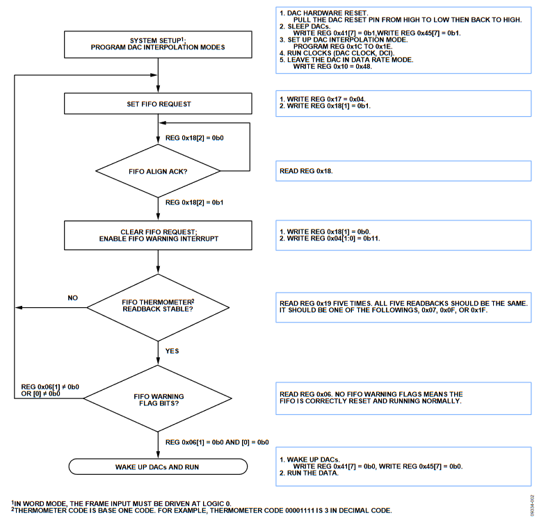
Figure 2. SPI Command Flowchart, Synchronization Off.
Data Rate Mode and FIFO Rate Mode with Synchronization On
Both the data rate mode and the FIFO rate mode achieve the same synchronization accuracy when synchronization is on. As described in the Data Rate Mode and FIFO Rate Mode with Synchronization On section, the difference between the two modes is how the FIFO is reset. Figure 3 illustrates the FIFO reset operation in the two modes. When synchronization is on, the read side of the FIFO is always synchronized to the sync clock.
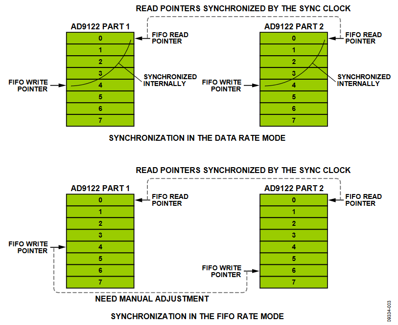
Figure 3. FIFO Reset Operation, Data Rate Mode vs. FIFO Rate Mode.
In the data rate mode, the write side of the FIFO is synchronized to the read side after the FIFO reset. If the same DCI, frame clock, DAC clock, and sync clock are shared between multiple AD9122 devices, the same input data is written into and read out from the FIFOs at the same time. Thus, the DACs are synchronized and their outputs are aligned.
The FIFO rate mode allows the write side of the FIFO to be reset at different times on different devices. In this mode, the read side of the FIFO is still synchronized to the sync clock so that the data is pulled out from the FIFO at the same time from the same slot. The write side of the FIFO can be reset at a different time, which means the same input data can be written into different slots in different devices.
Therefore, a manual adjustment on the FIFO phase offset (Register 0x17) is required in the FIFO rate mode. Despite this extra step, the FIFO rate mode is the recommended mode for synchronization due to its loose requirements on the timing of the clocks. A recommended sequence for FIFO rate synchronization is shown in Figure 4.
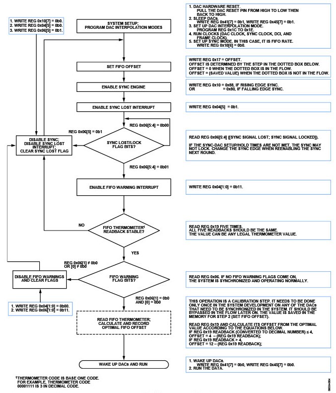
Figure 4. SPI Command Flowchart, FIFO Rate Mode, Synchronization On.
System Design Considerations for Synchronization
To achieve synchronization accuracy of one DAC clock cycle, the user must provide two clock signals, frame and sync clock, for the AD9122. Depending on the synchronization mode the user chooses, there are setup and hold timing requirements that need to be met (see Table 3).
| Sync Mode | Timing Requirements | Sync Clock Rate | Frame Clock Rate |
| FIFO Rate Mode | Sync clock—DAC clock setup and hold times | fDATA/8 or slower | fDATA/8 or slower |
| Data Rate Mode | Sync clock—DAC clock setup and hold times DCI—DAC clock setup and hold times |
fDATA or slower | fDATA/2 or slower |
In the synchronization state machine, the sync clock is sampled by the DAC clock to generate a reference point for aligning the internal clocks, so there is a setup and hold timing between the sync clock edges and the DAC clock edges. The AD9122 allows the user to choose either the rising or falling edge of the DAC clock to sample the sync clock, which makes it easier to meet the timing requirements.
There is a second setup and hold time requirement in the data rate mode if the FIFO is reset periodically. In this mode, the relationship between the DCI and DAC clock becomes critical. This timing constraint happens at the data rate, that is, the setup and hold timing window sits around the rising edge of the DCI. The rising or falling edge of the DAC clock, depending on which edge the user chooses to sample the sync clock, must be placed according to this timing requirement.
To achieve the targeted synchronization accuracy and meet the timing requirements, some decisions have to be made at the system level.
- Is a sync clock available at one eighth of the data rate?
- Is the sync clock generated by a clock chip or an FPGA/ASIC?
- Are the involved clocks (DAC clock, sync clock, and DCI) phase-locked in the system?
- How well are the clock traces matched?
The answer to the first question determines which synchronization mode to use. If such a clock is available, it is recommended that FIFO rate mode be used. The FIFO rate mode does not have a timing constraint on the DCI and DAC clock. This helps to simplify system design.
It is also recommended that the sync clock be generated by a clock chip, preferably the same clock chip that distributes the DAC clock. The clock chip provides a low jitter sync clock that is phase-locked to the DAC clock, which makes it easy to meet the sync clock and DAC clock timing requirements. If due to the restrictions in the system, the sync clock must be generated from a FPGA or ASIC, its jitter must be minimized. Large jitter can cause the sync logic to be unstable and thus corrupt the DAC output.
If the FPGA/ASIC is in a different clock domain than the DAC clock, to meet the sync and DAC clock timing, the FPGA/ASIC and the DAC clock must be locked to the same reference clock in the system. In the data rate mode, a similar phase locking requirement also applies to the DCI and DAC clock. Typically, the DCI is generated by an FPGA/ASIC. This requires the FPGA/ASIC to be locked to the DAC clock domain.
The trace mismatch has an impact on the synchronization accuracy and ability to meet the clock timing requirements. It is recommended that all the DAC clock traces be well matched to each other. The same requirements apply to matching the sync clock traces and DCI (frame clock) traces. There is no matching requirement across these clock domains. For example, if there are four AD9122 devices in the system, the DAC clock trace length, sync clock trace length, and DCI trace length are determined to be 6 cm (2.4 in.), 8 cm (3.1 in.), and 10 cm (3.8 in.), respectively. Notating these three traces of the first AD9122as L1DAC, L1SYNC, and L1DCI, the trace matching between the devices should be:
L1DAC = L2DAC = L3DAC = L4DAC = 6 cm
L1SYNC = L2SYNC = L3SYNC = L4SYNC = 8 cm
L1DCI = L2DCI = L3DCI = L4DCI = 10 cm
Any skew between sync clocks directly translates to a skew between DAC outputs. The skew between DAC clocks has the same impact on DAC outputs. Poorly matched traces make it hard to meet the timing over multiple DAC parts. This is because the equivalent setup and hold window over multiple parts is the union of the individual window on each part. The mismatch causes the individual window to shift from one another. The matching becomes more critical at high DAC rates where the available sampling window is smaller. It is recommended that the traces be matched within ±0.5 mm (±20 mil).
The following sections provide examples of latency variation calculation, hardware design, and software design given two AD9122 devices in the system, fDATA = 200 MSPS, 4× interpolation, in word interface mode.
Calculation of Latency Variation
The maximum skew between the DAC outputs of the two AD9122 devices is:

If the maximum skew between DAC outputs is within the system requirement, there is no need to synchronize the two parts, or to generate a sync clock and a frame clock. In this case, refer to the flowchart in Figure 2 to initialize the FIFO. If the system requires a smaller skew, the synchronization state machine needs to be turned on and the system must be designed so that it meets the timing requirements.
Hardware Design
In this example, use the AD9516 clock chip from Analog Devices, Inc. It has six LVPECL outputs and four LVDS/CMOS outputs. The LVPECL outputs have a programmable divider with the divide ratio up to 32. The LVDS/CMOS outputs have two such dividers, which provide a larger divider ratio. The LVDS/CMOS outputs also have a fine delay line that can be used to adjust the skew of a particular output with respect to the rest of the outputs. For detailed product information, refer to the AD9516 data sheet.
Assign two of the LVPECL outputs as the DAC clocks for the two AD9122 devices in this example. The DAC requires a very high quality and low jitter clock to achieve the specified performance. The synchronization requires very low skew between the DAC clocks. The excellent jitter and skew performance of the LVPECL signal serves this requirement well. Use an LVDS output as the sync clock for both AD9122 devices. The sync clock also requires a low jitter clock source for optimal synchronization accuracy. LVDS signal has very good jitter performance. More importantly, the fine delay line on the LVDS output in the AD9516 can be used to adjust the timing between the sync clock and DAC clock to make it easy to meet the setup and hold times. Use the FIFO rate synchronization mode and sync clock frequency of fDATA/8 = 25 MHz. Another LVDS output is assigned to generate a reference clock for the FPGA/ASIC. This ensures that the data and DCI clock from the FPGA/ASIC is phase-locked to the DAC clock.
The frame clock is generated by the same FPGA that generates the DCI and data. The frame clock is used to reset the FIFO in both devices. In this example, the rate of the frame signal is chosen to be 1/8 × fDATA. The rising edge of the frame should be aligned with the DCI as stated in the AD9122 data sheet. The data, DCI, and frame trace lengths of both AD9122 devices should be matched, as are the DAC clock traces and sync clock traces.
Software Design
The synchronization state machine is turned on through SPI commands in the AD9122. Before enabling the sync function, it is required that all of the involved clocks be in operation and stable. The flowchart in Figure 4 is the sequence to enable the sync engine and confirm the FIFO alignment in each AD9122. By successfully completing this sequence, the DAC outputs of the two AD9122 devices are aligned.
One-Time Synchronization Implementation
For the users who cannot implement the continuous synchronization scheme described in the System Design Considerations for Synchronization section, there is an alternative scheme that allows the user to perform a one-time synchronization on power-on or on a necessary basis. In one-time synchronization implementation, the sync engine is turned off after the DAC reaches synchronization status. Thus, the DAC does not track skew drifts in the system and does not report sync lock/unlock status to the user.
This may ease the timing requirements between the sync clock and the DAC clock with a slight loss in the synchronization accuracy, ±1 DAC cycle accuracy instead of within 1 DAC cycle. Steps must be followed in the flowchart shown in Figure 5 for implementing one-time synchronization.
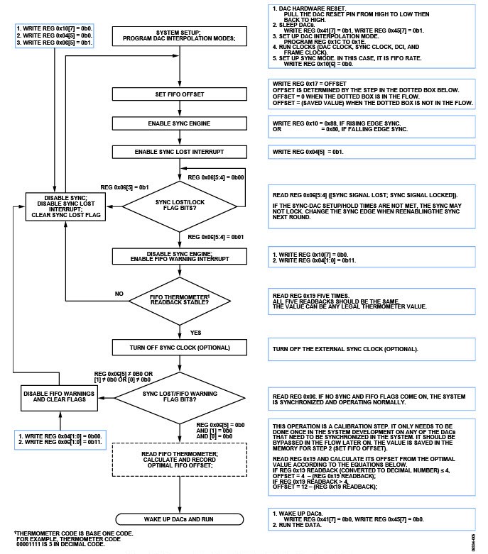
Figure 5. SPI Command Flow Chart, FIFO Rate Mode, One-Time Synchronization.
Conclusion
The AD9122 features a multichip synchronization function that is capable of synchronizing DAC outputs from multiple AD9122 devices within one DAC clock cycle. There are two synchronization modes, the data rate mode and the FIFO rate mode. These two modes achieve the same synchronization accuracy but have different system design requirements. The one-time synchronization option allows the user to turn off the synchronization engine after synchronization is achieved. Compared to the continuous sync mode, it has less accurate sync alignment and looser timing requirements in the system design.
