AN-035: CNC Motion with Ramp Generator
Approach
The classic CNC application uses a central CPU which tightly controls all axes. A structure could look like in Figure 1. In a stepper system, control is typically done by STEP & DIR signals, in order to allow lowest possible time delay between all axes, while using simple drivers. High resolution microstepping drivers are used to provide best precision and lowest operating noise. The disadvantage of this approach is that microstep drivers require fast microstep frequencies with tightly controlled frequency. For example, driving a 1.8° motor with a 16 microstep driver at 3 RPS, requires 9.6 kHz step rate. The best performance is yielded with equidistant steps. Any failure in the step equidistance can cause noise and increases vibration. Due to this, a theoretical interrupt rate equal to the required microstep frequency becomes necessary for step generation. As this is not possible for higher step frequencies, step generation often does multiple steps within one interrupt when the required microstep frequency for all motors exceeds the maximum allowable interrupt rate. This multi-stepping will lead to more coarse motor motion, vibration and noise.

Figure 1. Step & Direction interface based CNC control.
In order to take advantage of the integrated ramp generator, the internal calculations done in the CPU must be understood, and an intermediate result shall be used for controlling the motor in a way that relieves the CPU from additional fast real-time tasks like step generation. These intermediate results must be sent to the ramp generator in the right time. The required processing time and the moment in which the data must be sent depend on the working mode that we choose.
Ramp Description
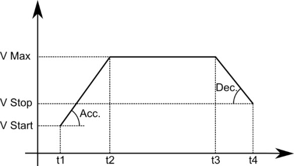
CNC and 3D typical software use trapezoid ramps to realize the movements described by the target positions of the model. The related parameters and important joints are shown in Figure 2.

Figure 2. Trapezoid Ramp.
The movement starts with the acceleration phase at t1 and with a start velocity until the maximum velocity is reached at t2. Afterwards, this velocity stays the same until t3, when the deceleration phase begins (acceleration and deceleration factors typically have the same value). At t4 the stop velocity is the last value when the motion segment ends. An upcoming new motion segment would be about to start with a start velocity equal to the previous stop velocity.
The area under the line represents the advanced position in that axis. When the movement is short, it might be necessary to reduce the maximum velocity until no plateau, i.e. constant speed phase, is present. In this case t2 and t3 would be the same moment.
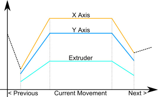
As seen in Figure 3, velocities and accelerations differ between axes, but t1, t2, t3 and t4 are constant for all of them.

Figure 3. Axis scaling.
The maximum speed and acceleration are calculated for the axis with a longer displacement in the movement, taking into account the hardware limitations and the maximum jerk in corner movements. The other axis are scaled down correspondingly. This is how all axes start and stop at the same time, but go over different distances.
The scaled parameters are calculated using the mechanical acceleration and velocity limits for each axis, the relative displacement of the axis and the sum of displacements of all axis. Some examples are shown in the following. Distances are given in microsteps, velocities in microsteps/s and acceleration in steps/s2.

The durations of the different phases can be calculated using basic cinematic formulas:

Velocity Mode
This is a straight-forward approach to reduce CPU workload, by offloading the step signal generation to the motion controller in the driver. The application benefits from the smoother motion, as the motion controller generates equidistant microsteps from the velocity setting.
The idea here is to skip the step generation inside the main CPU. Therefore, the internally calculated velocity information is fed to the drivers’ motion controller (see Figure 4) (VMAX register for velocity and RAMPMODE) for the direction. The motion controller accelerates to VMAX based on the acceleration setting. Additionally, the acceleration setting can be used for smoothening, i.e. by setting AMAX based on the change of velocity between each two updates. In case this is not desired, AMAX can be set to 65535. When combining this high AMAX setting with a reduced microstep setting (like 1/16 microstep with interpolation), extremely fast acceleration times result and thus the acceleration phase does not interfere with the calculated velocities. As in the original scheme, the main CPU needs to keep track of the actual positions, and do slight corrections to the velocity settings to avoid that the axis position slowly starts diverging from the assumed actual position. This correction function can run at reduced update rate, as basically the number of steps is the time integral over the velocity.

Figure 4. Velocity based motion control.
Implementation
For the implementation of this mode, the ramp can be divided into two parts: acceleration phase plus plateau and deceleration phase. The ramp controllers need to be given the new VMAX and AMAX in the correct point of time to start the new movement.
Using the formulas of Ramp Description Section, at t1 the processor must write the maximum speed in the VMAX register and the acceleration in the AMAX register of each controller. Then, the timer of the processor must start with a value equal to the delay of the acceleration phase and the plateau. The ramp controller will increase the velocity from the current one (start velocity) until the written in VMAX (reached at t2). This speed will be kept until the next change.
When the timer expires (at t3), the processor writes the final velocity to VMAX so that the controller starts decelerating. The time will be equal to the duration of the deceleration phase.
Position Mode
This approach saves even more real-time CPU resources, as motion segments are only prepared by the CPU, but are executed by the drivers’ motion controllers. The only real-time critical part is the start of the motion. The motion start for all axes included in a motion segment shall be executed in a quick sequence for all motor axes. Therefore the approach is especially good for applications, which allow a very limited update rate only due to low CPU resources.
The idea here is to directly use position and velocity ramp information available in the main CPU, and leave interpolation on a fine grid to the motion controller in the TMC5xxx driver. This will not only skip the step generation inside the main CPU, but allows the CPU to prepare the next segment, while the previous segment is executed, or even do preparations in advance. Each motion segment prepared by the CPU shall contain a start velocity, a stop velocity, a maximum velocity, and acceleration and deceleration values as well as the displacement. The next segment shall start just before the previous segment has been completely executed. This way, the segments can be attached seamlessly, without motor stop in between. The ramp controller will automatically accelerate depending on the difference between the actual positon and the target position, and decelerate when it comes near to the end of the motion segment. With VSTOP of the previous segment identical to VSTART of the subsequent segment, a continuous motion is achieved.
This way, the calculated position is a means to fully control the motor by feeding a sequence of positions, velocities and acceleration / deceleration for smoothening (see Figure 5). Only values which are changed need to be written to the motion controller using the SPI interfaces.

Figure 5. Velocity based motion control.
In order to start the next ramp segment, there are two options. Option 1 uses the CPU timer to issue an interrupt for starting the next segment. Therefore the CPU calculates the time required for each motion segment and issues an interrupt, just before the segment is planned to finish. The interrupt procedure will program the next segment for seamless motion. Option 2 uses the position interrupt of one motor axis controller involved in the motion (e.g. the axis with the highest motion distance), to issue an interrupt in time before the target position is reached (e.g. a few microsteps in advance, which will leave enough time to safely update all motion controllers). This way the next motion segment starts during the (end of the) slow-down ramp going down to VSTOP. When it receives the new target position and velocity and acceleration set, the motion controller will take care of doing a longer deceleration phase or appending the acceleration phase earlier. This even allows an update-uncertainty of many microsteps, without influencing the quality of the motion output and thus relaxes the interrupt latency time required within the CPU.
This way, the motion profile is converted to the motion controller units, and the motion controller will execute the complete ramp.
Note: A potential time lag between update of the different motion controllers will be in the microseconds range. This will give less than one microstep, even for a 256 microstep application. It could also be pre-compensated for, as the time sequence of the SPI transfers is well-known.
Implementation
This time, the processor writes all the parameters at once for the whole ramp. That is why it is a good idea to pre-calculate them while the ramp controllers are working and the timer on the processor is running (if the approach is to use target-reached flags, no timer will be required).
At t1, the processor must write the acceleration in AMAX and DMAX registers, the initial, maximum and final speeds in VSTART, VMAX and VSTOP, and finally the final position into X_TARGET. The timer must be set here to the sum of the three movement phases.
In order to use a linear ramp with single acceleration, the V1 threshold velocity becomes set to zero. D1 and A1 can be set to a maximum value, different from 1. As the style of motion used often requires setting high acceleration values, the 16 bit acceleration range might impose a limit. In this case, a practical implementation might use 1/16 microstep setting of the sequencer with automatic interpolation to 256 microsteps. Despite this mode is normally reserved for STEP/DIR interfaces, it is beneficial for motion controller use in order to effectively yield a 16 times higher range for acceleration and deceleration.
Summary
While the original control needs step rates of a few 10 kHz per motor to operate the stepper within a reasonable velocity range, the velocity mode scheme can work with reduced update rates of a kHz or even less, when taking advantage of the acceleration phase. The position mode scheme will avoid the feedback loop from the CPU to the motion controller and the interrupt rate goes down to one interrupt per motion segment, i.e. well below 1kHz even when plotting circles. The precision of the application can be improved by using a higher microstep resolution while no additional CPU resources are required. The benefit of both variants is that they run absolutely smoothly, even at high velocity, thanks to the use of dedicated motion hardware.
Real time data transmission
Programming a register within the TMC5xxx family driver requires 40 SPI bits to be send. Assuming 4 MHz SPI rate, which is well below the IC limit, this will require about 10µs. This ways, a number of ICs and parameters can quickly be set, and the delay between the accesses to the different controllers is negligible. It even can be compensated for by software. As an option, in order to reach a real zero delay, all drivers can be put into a single SPI chain. However, this will require an n-times 40 bit SPI datagram to be sent for each access, even when accessing a single driver, only.
