资源库
AN-003: dcStep™ Basics and Wizard
The TMC5062 dual driver/controller family, as well as the TMC5130 single driver & controller IC and the TMC2130 stepper driver, offer a powerful feature to extend the usage range of a stepper motor: dcStep. dcStep is a load dependent speed control. The motor moves as fast as possible and never loses a step. dcStep basically requires tuning of a single parameter and setting of a lower operating velocity. The application note and the Wizard intend to give you a feeling for the parameters and their effect.
What is dcStep
Stepper motors are typically used below their maximum pull-out torque with a safety margin of 40-50%. A safety margin of up to 50% torque is required in order to compensate unforeseen load peaks, torque loss due to resonance, and aging of mechanical components in an open loop system. Furthermore, stepper motors lose torque at higher speeds due to the specific dependency of rotor velocity and back EMF.
If load becomes too high, stepper motors lose steps and may even stall completely. This requires provisions to monitor motor movement and to recognize/prevent motor stall. Typically, various types of position encoders are used, each with their specific pros, cons and costs.
dcStep is a new, efficient, stepper motor commutation scheme that focuses on utilizing most of the available output torque (ca. 80%) of the stepper motor. With dcStep, a stepper motor behaves like a DC motor if the load exceeds the motor output torque for the actual working point. It automatically adapts the motor velocity to the actual load by moving along the shape of the stepper motor torque curve. Due to this automatic load dependent deceleration and acceleration, the stepper motor does not lose any steps or stalls with the tradeoff of having a varying velocity. Nevertheless, it will arrive at the target position in any case without step loss. That is, dcStep keeps load and torque in balance.
dcStep is sensorless and thereby cost-neutral
dcStep is based on full step excitation and is most efficient at middle to high speeds. When analyzing typical stepper motor torque curves, the maximum output torque does not increase significantly in the lower speed regions when decelerating, but is more or less constant and further deceleration does not provide additional advantage. Thus, dcStep is used in the middle and higher speed regions where the back EMF impacts motor coil current and maximum output torque significantly.
For a given setup and application, dcStep extends the stepper motor’s functional area by either allowing for more torque output in the same working point (same velocity) or by increasing the maximum velocity. In some cases and depending on the application, a smaller and cheaper motor may do the same job.

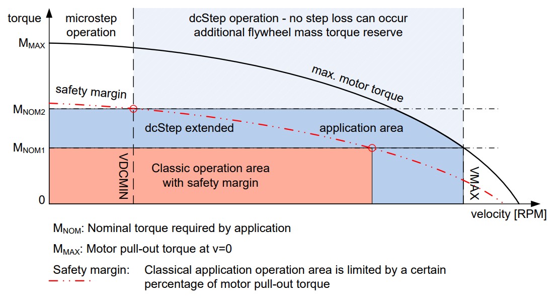
Figure 1.
dcStep Operating Modes
dcStep can be used in different ways:
- Speed limited: If the target velocity is limited by a motion controller, the motor is not necessarily operated at its torque limit. It still has some torque reserves left. In combination with coolStep (not possible with the TMC5062), the motor current can be reduced to the actually required value in order to save energy. With increasing load it does not decelerate immediately. Only when the load exceeds the output torque it starts deceleration to keep load and torque in balance.
- Load limited: If the target velocity is not limited (or very high), the motor is always operated at its limit and every load change is visible in a changing motor speed. Output torque and load are always balanced here.
- Minimum allowed velocity is > 0. dcStep is tuned for highest torque output (at high velocities). In this case, the motor cannot decelerate down to zero, but only to VDCMIN. This is the natural use case of dcStep, because the torque does not significantly increase any further below this minimum velocity. Focus is on exploiting the maximum torque in the higher speed regions.
- Minimum velocity is = 0. Here, the focus is not primarily on maximum torque output but on deceleration down to
zero and automatic ramp up when load will decrease.
- Using the dcStep stall/stop detection in the TMC5130, a stall/stop condition can be detected, and the motor stops automatically
- When tuning the setting for a very low operation velocity, higher velocities cannot be reached.
Limitations of dcStep™
- Actually, the dcStep slogan is “as fast as possible”. Nevertheless, this does not mean that a stepper motor can be used at very high speeds comparable to a brushless DC motor (BLDC, PMSM). “As fast as possible” means that the stepper motor can run at the maximum speed that is possible according to the load applied to the motor shaft and according to the parameter settings and motor supply voltage.
- dcStep does not replace an encoder. dcStep is still an open loop mode. If load is just too high and the speed falls below the minimum speed VDCMIN, the motor may stall and lose steps. However, stallGuard detects and reports this situation reliably. With an optional encoder, one could additionally track the position.
- dcStep allows for efficient utilization of the maximum stepper motor pull out torque without providing a safety margin. This again may allow replacing the original motor with a smaller and cheaper motor for the same application to safe costs. This cannot be guaranteed for every application and strongly depends on the application and the original motor type. A NEMA34 motor cannot be replaced with a NEMA17 motor for example because the difference between these two motors is just too big.
- dcStep cannot use 100% of the motor’s maximum output torque but approximately 80% to 90% before slowing down the motor to a lower speed. This results from the necessity of some safety margin, to compensate for tolerances. However, this is still much more than the torque which may safely be used in an open loop system.
Supported Products
Trinamic stepper motor driver ICs allow for automatic and seamless switching from microstepping excitation during ramp up and ramp down to dcStep mode when exceeding the configured velocity limit VDCMIN. This still allows positioning moves with highest microstep precision (256 µSteps per full step) while exploiting the motor torque during constant speed phase.
Another reason for doing so is that especially in the lower-speed regions, microstep operation is superior to full step operation because of resonance dampening and slightly higher torque output. Whereas full step operation allows for slightly higher torque output in the high speed region compared to microstep operation.

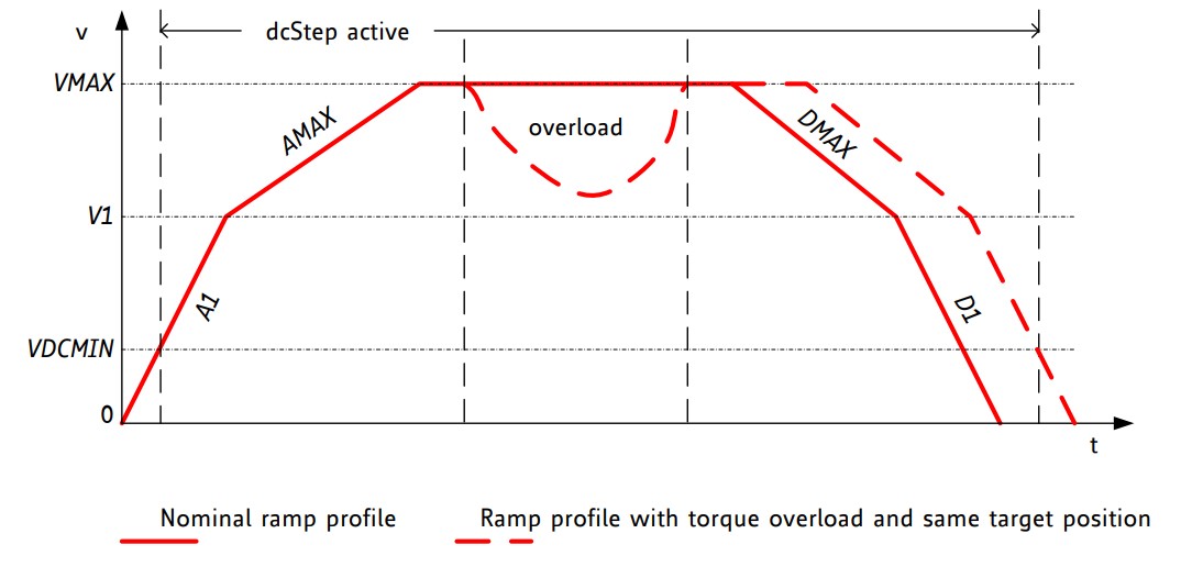
Figure 2.
The following ADI Trinamic products (integrated controller+driver) support dcStep with seamless switching to and from microstepping:
- TMC5062
- TMC5072
- TMC5130
The following ADI Trinamic products (dedicated controller and dedicated driver/predriver) support dcStep in combination
- TMC4361 + TMC26x
- TMC4361 + TMC2130
Tuning Procedure
Parameters
A number of parameters are required to activate dcStep. Motor and supply voltage specific tuning is required for DC_TIME and DC_SG. Also, the clock frequency of the IC should not be changed after tuning, because the parameters internally are mapped to different timing constraints. As DC_TIME influences the lower operation velocity limit of dcStep, VDCMIN must be tuned after each change done to DC_TIME.
| Parameter | Description | Range | Comment |
| vhighfs & vhighchm | Activate to enable dcStep compatible chopper mode | 0 / 1 | set to 1 for dcStep |
| TOFF | dcStep requires a stable chopper for optimum operation. With a chopper not using fast decay, an increased slow decay time helps fulfilling this. Therefore, TOFF should be set to 8 initially. Later on, smaller values can be tried out. | 2 to 15 | Settings 8 to 15 do not make any difference to setting 8 for dcStep operation. |
| VDCMIN | This is the lower threshold for dcStep operation when using internal ramp generator. Below this threshold, the motor operates in normal microstep mode. In dcStep operation, the motor operates at minimum VDCMIN, even when it is completely blocked. Tune together with DC_TIME setting. When DC_TIME is increased, typically a higher VDCMIN is required | 0 to 2^22 | 0: Disable dcStep Set to the lower velocity limit for dcStep operation. |
| DC_TIME | This setting should be optimized for robust
operation with maximum motor torque. A higher
value allows higher torque and higher velocity, a
lower value allows operation down to a lower
velocity as set by VDCMIN.
Check best setting under nominal operation conditions, and re-check under extreme operating conditions (e.g., lowest operation supply voltage, highest motor temperature, and highest supply voltage, lowest motor temperature). |
0 to 255 | Lower limit is tBLANK (as defined by TBL) in clock cycles + 1 |
| DC_SG | This setting controls stall detection in dcStep
mode. Increase for higher sensitivity.
A stall can be used as an error condition by issuing a hard stop for the motor. Enable sg_stop flag for stopping the motor upon a stall event. This way the motor will be stopped once it stalls. The stall detection should be enabled once the motor has exceeded a certain lower velocity. This will prevent the driver from detecting false stall events during acceleration in resonance areas. |
0 to 255 | Set slightly higher than DC_TIME / 16 |
dcStep Tuning
The setup of dcStep requires some optimization. Please see the flow chart for the basic procedure. Additional loops may be required in order to get the best feeling for the parameters and the motor.

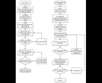
Figure 3.
Using the Wizard
The TMCL-IDE brings a Wizard for tuning dcStep. The Wizard activates the required parameters in the right order and helps understanding dcStep and getting a feeling for its operation.
PREREQUISITES
Before launching the Wizard, the basic settings should have been made: Motor current (fitting to the motor) and initial settings for the spreadCycle™ chopper, which becomes activated during the first acceleration phase.

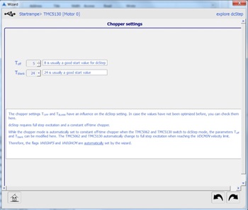
Figure 4. FIRST STEP: CHECK TBL AND TOFF.
As dcStep generally requires higher TOFF settings, while it benefits from lower TBLANK settings, a first step is to check if the settings applied should be modified. In case they have been optimized before, revert to the desired settings.

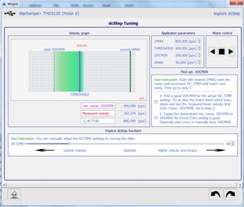
Figure 5. SECOND STEP: OPTIMIZE SGT TOGETHER WITH VDCMIN.
Now, start the motor by pressing the rotate right or rotate left button. Adapt AMAX if the motor cannot start up. If the motor does not accelerate when increasing DCTIME, decrease VDCMIN. In this case probably the motor already has reached the maximum dcStep velocity with the given current setting.
Now, activate the first round button. This will set a very low VDCMIN, allowing tests within the full motor velocity range. Manually apply force to the motor and try braking it. You will experience a lower velocity, below which the motor does not run smoothly anymore. This lower velocity shifts up with higher DCTIME. At the same time, also the upper velocity limit shifts up, and torque available at higher velocity. Find a good trade-off between lower velocity limit and torque at the desired VMAX.
In step 2, the lower measured velocity becomes copied to VDCMIN. In case it is too low, you can go back to step 1, or manually increase it.

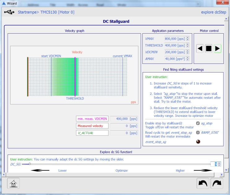
Figure 6. THIRD STEP: OPTIMIZE SGT TOGETHER WITH VDCMIN.
In this step, dcStep stallGuard becomes tuned to fit the determined settings. Hook sg_stop and try to stall the motor. The driver now will stop the motor in case it detects a complete stall. In case it stops too early, decrease DC_SG. In case it does not stop, or only after losing several steps, increase DC_SG. To reset the stop condition, either remove sg_stop, or check RAMP_STAT. This will read out RAMP_STAT and signal when a stop was detected, while at the same moment restarting the motor.
In case the motor cannot restart safely with the actual settings, reduce DC_SG or increase the stallGuard threshold velocity (THRESHOLD).
Go to the last step to see the results screen and copy them to your application.
作者
