Versatile Op Amps Need No Resistors
Introduction
The LT1990, LT1991 and LT1995 are ready-to-use op amps with their own resistors and internal compensation capacitors. Many difference or instrumentation amps offer precisely matched internal components, but such devices are usually designed to solve a specific application problem, and thus have limited versatility. Not the LT1990, LT1991, and LT1995. These are flexible parts that can be configured into inverting, non-inverting, difference amplifiers, and even buffered attenuators, just by strapping their pins (Figure 1).

Figure 1. What could be easier? A precision difference amplifier; no resistors in sight. This is only one of hundreds of possible configurations. See Figure 3 for a few more.
The internal precisely matched resistors and capacitors make it possible to configure these op amps into hundreds of different application circuits without external components. Simply hook them up for type and gain and move on. By reducing the external components in your design, you simplify inventory, reduce pick and place costs, and make for easy probing.
What Do You Need:
High Precision, High Input Voltage or High Speed?
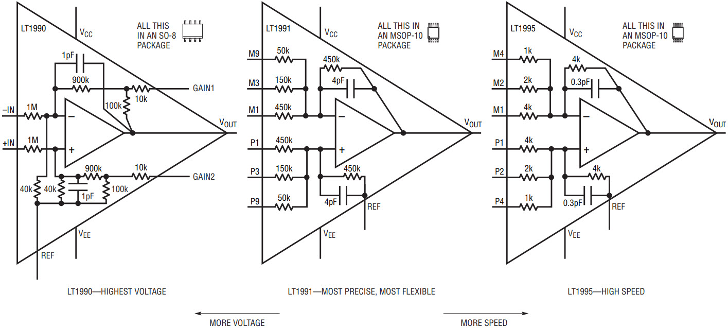
Figure 2 shows simplified schematics of the three new amplifiers and in general, their comparative performance. The LT1990 is optimized for supporting high input common mode voltages of up to ±250V. The LT1991 is optimized for gain flexibility and overall precision, and supports common mode ranges up to ±60V. The LT1995 is designed for high speed applications up to 30MHz.

Figure 2. The LT1990, LT1991, and LT1995 are ready-to-use op amps with their own resistors and internal compensation capacitors. Just wire them up.
The LT1991 for the Greatest Flexibility and Precision
The LT1991 is the most flexible and most precise of the three new devices. Its internal resistors guarantee 0.04% ratio-matching and 3ppm/°C MAX matching temperature coefficient. The op amp offers 15µV typical input offset voltage and 50pA of input offset current. The LT1991 operates on supplies from 2.7V to 36V with rail to rail outputs, and remains stable while driving capacitive loads up to 500pF. Gain bandwidth product is 560kHz, while drawing only 100µA supply current.
The resistors are nominally 50k, 150k, and 450k. One end of each resistor is connected to an op amp input,and the other is brought out to a pin. The pins are named “M” or “P” depending on whether its resistor goes to the “minus” or “plus” input, and numbered “M1” M3” or “P9” etcetera according to the relative admittance of the resistor. So the “P9” pin has 9 times the admittance (or force) of the “P1”pin. The 450k resistors connected to the M1 and P1 inputs are not diode clamped, and can be taken well outside the supply rails, ±60V maximum.
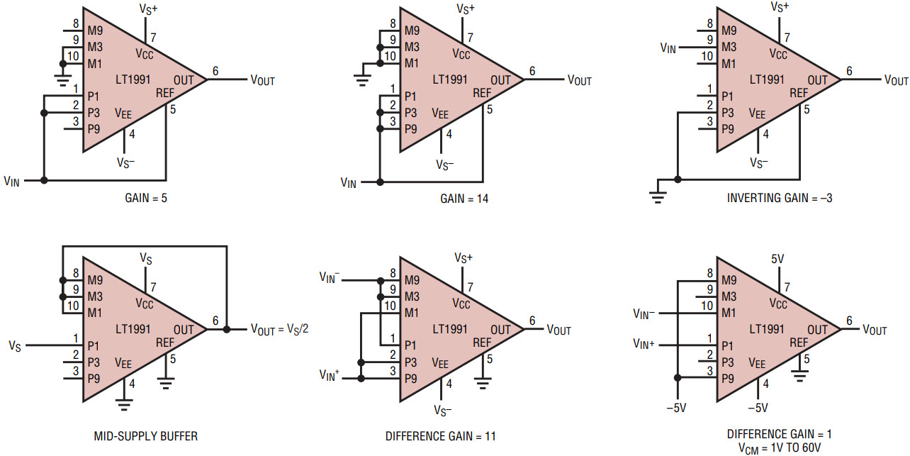
To use the LT1991, simply drive, ground or float the P, M, and REF inputs to set the configuration and gain. There is a whole series of high input common mode voltage circuits that can be created simply by just strapping the pins. Figure 3 demonstrates the flexibility of the LT1991 with just a few examples of different configurations and gains. In fact, there are over 300 unique achievable gains in the non-inverting configuration alone. Gains of up to 14 and buffered attenuations down to 0.07 are possible.

Figure 3. Non-inverting, inverting, difference amplifiers, and buffered attenuators achieved simply by connecting pins. This illustration shows only a small sample of the op amp configuration circuits possible with the LT1991, all without requiring external resistors.
The LT1990 for High Input Voltages
The LT1990 has internal components with similar precision to the LT1991, but it is configured for high input voltages, up to ±250V. The high input voltage capability is achieved by the 1MΩ:40kΩ attenuation at the inputs, and by careful internal layout and shielding. The LT1990 has two effective gain settings, 1 and 10. A gain of 1 is set by floating the Gain1 and Gain2 pins, and again of 10 is set by shorting the Gain1 and Gain2 pins. Bandwidth is 100kHz in a gain of 1, and 6.5kHz in a gain of 10. The op amp operates on supplies from 2.7V to 36V with rail to rail outputs, on 105µA supply current. Like the LT1991, it remains stable while driving capacitive loads up to 500pF.
The LT1995 for High Speed
The LT1995 offers high speed with 30MHz bandwidth, 24MHz full power bandwidth and 1000V/µs slew rate. It works on supplies from ±2.5V to ±15V drawing 7mA supply current. Accuracy is unusually good for a high speed amplifier, with input offset typically 600µV and guaranteed better than 4mV. It is pinned out identically to the LT1991, but with different resistor ratios and values. The resistors are lower impedance (1k, 2k, and 4k) than those in the LT1991 and LT1990 to support this device’s higher speed. They areas high a quality as you should ever need in a high speed application, guaranteeing 0.25% matching, worst case over temperature. As with the LT1991, the LT1995 takes its pin names from the relative admittances of their resistors and the amplifier input polarity: hence “M1”, “M2”, “P4”, etcetera. For a difference gain of 6, short the M2 and M4 pins, and short the P2 and P4 pins (2 + 4 = 6). In this example, the difference amplifier is formed by the minus input of the shorted M2 and M4 inputs, and the plus input of the shorted P2 and P4 inputs.
Applications
Battery Monitor
Many batteries are composed of individual cells with working voltages of about 1.2V each, as for example NiMH and NiCd. Higher total voltages are achieved by placing these in series.The reliability of the entire battery pack is limited by the weakest cell, so battery designers often like to maintain data on individual cell charge characteristics and histories.
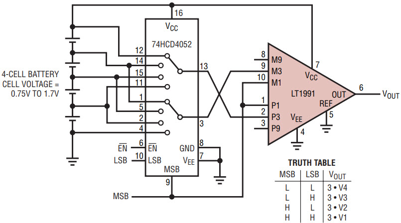
Figure 4 shows the LT1991 configured as a difference amplifier in a gain of 3, applied a cross the individual cells of a battery through a dual 4:1 mux. Because of the high valued 150kΩ resistors on its M3 and P3 inputs, the error introduced by the multiplexer switch ON-resistance is negligible. As the mux is stepped through its addresses, the LT1991 takes each cell voltage, multiplies it by 3, and references it to ground for easiest measurement. Note that worst case combinations of very different cell voltages can cause the LT1991 output to clip. Connecting the MSB line to the M1 and P1 inputs helps reduce the effect of the wide input common mode fluctuations from cell to cell. The low supply current of the LT1991 make sit particularly suited to battery powered applications. Its 110µA maximum supply current specification is about the same as that of the CMOS mux!

Figure 4. LT1991 applied as an individual battery cell monitor for a 4-cell battery.
Single-Supply Video Driver
Most op amps operating from a single supply voltage require several high quality external resistors to generate a local bias voltage—to optimize the DC operating-point—and resistors to set gain. High quality resistors consume precious printed circuit board real estate, and test time. In contrast, the LT1995 provides on-chip resistors for voltage division and gain setting in a highly integrated video-speed op amp.
Figure 5 shows a simple way to drive AC-coupled composite video signals over 75Ω coaxial cable using minimum component count. In this circuit, the input resistors form a supply splitter for biasing and a net attenuation of 0.75. The feedback configuration provides an AC-coupled gain of 2.66, so that the overall gain of the stage is 2.0. The output is AC-coupled and series back-terminated with 75Ω to provide a match into terminated video cable and an overall unity gain from signal input to the destination load. An output shunt resistor (10kΩ in this example) is always good practice in AC-coupled circuits to assure nominal biasing of the output coupling capacitor.

Figure 5. This single-supply composite video output-port driver requires no DC-biasing or gain-setting resistors.
Full Bridge Load Current Monitor
Many new motor-drive circuits employ an H-bridge transistor configuration to provide bidirectional control from a single-voltage supply. The difficulty with this topology is that both motor leads “fly,” so current sensing becomes problematic. The LT1990 offers a simple solution to the problem by providing an integrated difference amp structure with an unusually high common-mode voltage rating, up to ±250VDC.


