要約
A quad, low-noise, op amp and LDO are used to build a stereo preamp with RIAA equalization to allow converting signals from a record player (phonograph) to a linear output for digitizing by computer sound cards etc.
A phono preamp is needed for preamplifying and equalizing the analog output of the good old record player. The former hi-fi amplifiers or stereos included a phono input, but at this time it is not very common because the CD player has a linear output and doesn't need linearization. If you still want to play your records or you want to archive LPs with a soundcard on your computer you will need this phono preamp. This application is easily powered by +5V the USB port supply. No external power supply, dual supply, or wall cube is needed.
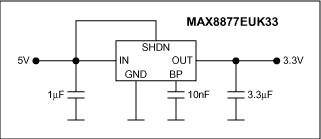
This design idea shows a 3.3V powered phone preamplifier with RIAA equalization curve. The advantage is the low power, low voltage single supply solution. It is done with a MAX4478, a quad, low-noise, rail-to-rail op amp. A small linear regulator, the MAX8877, regulates the noisy +5V from the USB supply down to +3.3V (see Figure 1.)

Figure 1. +5V USB power supply with +3.3V output.
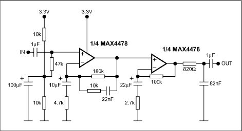
Additionally, the MAX4478 op amp offers a very high power supply rejection ratio of 120dB. This circuit is intended for use the standard moving magnet type phono pickup (see Figure 2).

Figure 2. One channel phono preamplifier with RIAA equalization.
The high value capacitors with 100µF, 22µF and 10µC could be tantalum or standard electrolytic caps. The low value capacitors with 82nF and 22nF should be 2.5% tolerance, if obtainable, otherwise you may be able to measure a selection of standard tolerance caps to find those which are closest to the required value. Some deviation from the ideal RIAA equalization curve will occur if these caps are too far from the designated values (see my test). More important is matching between channels—this should be as accurate as possible.
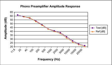
Resistors should be 1% metal film for close tolerance and low noise. This design is done with an active low frequency and a passive high frequency filtering. Based on the RIAA specification Table 1 shows the performance with frequency. There is no rumble filter for frequencies below 20Hz integrated. Please be careful with 50Hz-60Hz noise. The application has a high amplification for low frequencies. It is about 60dB (1000) for 20Hz.
As can be seen from Table 1 or Figure 3, the accuracy is about 1dB. This might be increased if a more accurate capacitor for the high-frequency filtering is used. The gain at 1kHz is about 40dB (100) so a nominal 5mV cartridge output will give 500mV output. This may be increased if necessary, by increasing the value of the 100k resistor in the second stage.
| Frequency (Hz) | Test (dB) | Ref (dB) | Error |
| 11,8 | 61,4 | ||
| 20 | 59,17 | 59,3 | 0,13 |
| 40 | 57,44 | 57,8 | 0,36 |
| 100 | 53,63 | 53,1 | -0,58 |
| 200 | 48,52 | 48,2 | -0,32 |
| 500 | 43,12 | 43,2 | 0,08 |
| 1000 | 40,83 | 40,0 | -0,83 |
| 2000 | 38,41 | 37,4 | -1,01 |
| 5000 | 33,23 | 31,8 | -1,48 |
| 10000 | 27,82 | 26,3 | -1,52 |
| 15000 | 23,85 | 22,8 | -1,05 |
| 20000 | 21,53 | 20,4 | -1,13 |

Figure 3. Frequency response vs. RIAA reference.


