要約
The high number of LED applications in modern automobiles creates space problems, requiring high integration and high efficiency. The wide variety of LED lighting applications can create problems such as reduced purchasing power due to low volumes, longer design cycles, and longer time to market. The MAX25610A is a flexible, highly integrated automotive LED driver that can easily be configured to implement buck, buck-boost, and boost topologies, thereby covering a large class of automotive LED applications.
Introduction
Automotive LEDs have taken the industry by storm thanks to their versatility and efficiency. In automotive lighting applications, LEDs power the car headlights, tail lights (Figure 1), and just about anywhere they are needed inside or outside the automobile for style and function. Infrared (IR) LED diodes are used in driver monitoring systems (DMS). GPS navigation and in-cabin entertainment displays utilize strings of LEDs for backlighting.
These LED applications must be small and efficient enough to fit in the existing space without overheating. With so many different functions, one might expect the automobile manufacturer to be resigned to stocking a large quantity of different automotive LED drivers. This can have severe implications in terms of reduced purchasing power due to low volume orders, longer design cycles, and delayed time to market.
Is it possible to have an efficient, highly integrated automotive LED driver that is flexible enough to cover the majority of these applications? This design solution reviews the power requirements of three classes of LED lighting applications and points to the optimal LED driver topology for each case (buck, boost, buck-boost). It then introduces an innovative solution to meet their integration, efficiency, and flexibility challenges.
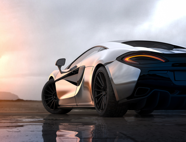
Figure 1. Sports car tail light detail.
In-Cabin Light Applications
In-cabin applications like overhead and vanity lights, including driver monitoring systems, require one or two LED diodes for operation. For a typical LED diode that develops 3.5V at 1A, this type of application can be well served by a simple buck converter. In Figure 2, the buck-converter inductor current builds up when N1 is ‘on’ and is maintained ‘on’ through N2 when N1 is ‘off.’ Synchronous rectification accounts for the high efficiency.
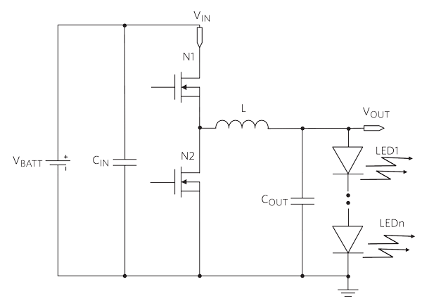
Figure 2. Buck converter in a typical LED driver configuration.
Exterior and Signaling Applications
Daytime running lights, tail lights, fog lights, and turn indicators require at least three or four LED lights to operate. Here, the voltage ranges from 10.5V to 14V. With the car battery varying from less than 6V (cold crank) to 16V, the best configuration for this type of application is a buck-boost converter. One example of a buck-derived buck-boost implementation is shown in Figure 3. Notice how the output voltage is always below ground. The inductor builds up current when N1 is ‘on’ and is fed through N2 when N1 is ‘off.’ The voltage across the inductor inverts at each transition, independently of the number of diodes. Accordingly, this configuration can operate with any number of diodes on the output, and a string voltage drop that adds up to a value that is above or below the input voltage (buck-boost operation).
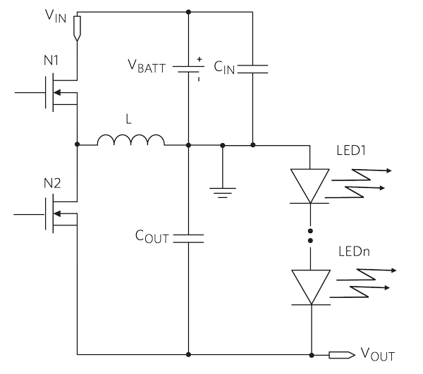
Figure 3. Buck-derived buck-boost operation.
Low/Mid-Power Headlights and In-Cabin Display Applications
Low/mid-power, high-beam and low-beam headlights, as well as in-cabin displays for GPS navigation and entertainment, require long strings of diodes. For this application, the best configuration is the boost converter. In the buck-derived boost converter of Figure 4, the output voltage floats below the input voltage. The inductor builds up current when N1 is ‘on’ and is fed through N2 when N1 is ‘off.’ For the voltage across the inductor to invert at each transition, the number of diodes must be high enough so that the output voltage is negative with respect to ground. For this reason, the configuration can only operate with a high number of diodes in the string, in this case, 8 (28V string).
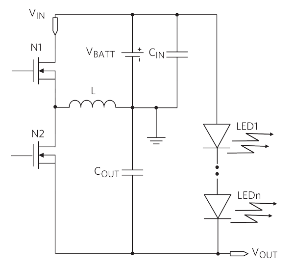
Figure 4. Buck-derived boost operation.
A Catch-All Solution
Buck, boost, and buck-boost canonical implementations can be very different and very difficult to reconcile in a single IC. However, in automotive LED applications it makes no difference where the string is voltage-referenced. This opens the opportunity to adopt a buck-derived topology for both the buck-boost and boost converter. In the above three examples, the cathode of the LED’s bottom diode is opportunistically referenced to ground (buck) or VOUT (buck-boost and boost) while the anode of the LED’s top diode is referenced to VOUT (buck) or ground (buck-boost and boost). Indeed, it is possible in this application to have a single flexible topology for all cases, with minor adjustments of the IC and the application configuration.
Integrated, Flexible Solution
The IC in Figure 5 is a fully synchronous LED driver that provides constant output current to drive high-power LEDs. The IC integrates two 60mΩ power MOSFETs for synchronous operation, high efficiency, and minimum number of external components. Flexible configuration supports buck, inverting buck-boost, and boost conversion. The devices can operate in two modes. For buck mode, connect a 2.49kΩ resistor from VCC to the PWMFRQ pin. For buck-boost or boost mode, connect a 17.8kΩ resistor from VCC to the PWMFRQ pin.
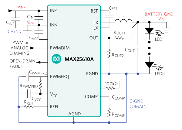
Figure 5. Integrated, flexible converter in buck-boost mode.
Flexible Dimming
The LED driver offers an analog dimming-control input pin (REFI) while the voltage at REFI sets the LED current level linearly from zero up to maximum when VREFI = 1.3V.
In addition, the device offers PWM dimming. PWMDIM functions with either analog or PWM control signals. Once the internal pulse detector detects three successive edges of a PWM signal with a frequency, the device synchronizes to the external signal and pulse-width modulates the LED current at the external PWMDIM input frequency and duty cycle. If an analog control signal is applied to PWMDIM, the device compares the DC input to an internally generated 200Hz ramp to pulse-width modulate the LED current.
An integrated current-sense capability saves from using an external sense resistor, which reduces PCB space and cost. Integrated MOSFETs allow for well-controlled transition fronts, minimizing EMI. Built-in spread spectrum allows for further EMI noise reduction. The IC is offered in a 16-pin 5mm x 5mm SWTQFN and in a 5mm x 6.4mm TSSOP package.
Conclusion
The high number of LED applications in modern automobiles creates space problems, requiring high integration and high efficiency. The wide variety of LED applications can create problems such as reduced purchasing power due to low volumes, longer design cycles, and longer time to market. The MAX25610A is a flexible, highly integrated automotive LED driver that can easily be configured to implement buck, buck-boost and boost topologies, thereby covering a large class of automotive LED applications. On-board power MOSFETs with low RDS(ON) support synchronous operation, reduce PCB space, and yield high efficiency for lower heat generation. This innovative LED driver IC solves the challenges of space, purchasing volumes, and cycle times.


