SMBus Controlled CCFL Power Supply
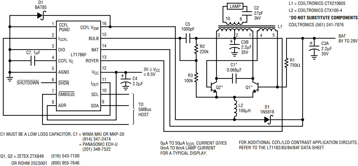
Figure 1 shows a cold cathode fluorescent lamp (CCFL) power supply that is controlled via the popular SMBus interface. The LT1786 CCFL switching regulator receives the SMBus instruction. The IC converts this instruction to a current, which appears at the IOUT pin. This current, routed to the ICCFL pin, provides a set point for switching regulator operation. The resultant duty cycle at the VSW pin pulls current through L2. L2, acting as a switched current sink, drives a resonant Royer converter composed of Q1–Q2, C1 and L1. The high voltage sine wave produced at L2’s secondary drives the floating lamp.

Figure 1. 90% efficient floating CCFL with 2-wire SMBus lamp-current control.
Current flow into the Royer converter is monitored by the IC at pin 13 (“Royer” in Figure 1).1 Royer current correlates tightly with lamp current, which, in turn, is proportional to intensity. The IC compares the Royer current to the SMBus-derived current, closing a lamp-intensity control loop. The SMBus permits wide-range regulated lamp-intensity control and allows complete IC shutdown. Optimal display and lamp characteristics permit 90% efficiency. The circuit is calibrated by correlating SMBus instruction codes with attendant RMS lamp current. Detailed information on circuit operation and measurement techniques appears in the references below.
Note:
1 Local historians can’t be certain, but this may be the only IC pin ever named after a person.


