Read other articles in this series.
要約
Electronic system errors are typically analog, not digital. Analog is prone to signal-to-noise, crosstalk, and linearity issues. This application note discusses the need for power and ground cleanliness and integrity. Analog interface can be a trap for many designs, so examples show how to use existing ICs to overcome common analog issues.
Introduction
Washing our hands seems to be simple common sense. It has often been said that many preventable diseases still exist because of human error—failure to wash hands and take logical safety precautions regularly.
Now you ask, what has hand washing to so with electronic IC design? Many times electronic system failures are blamed on the parts when the real cause was human error. Of these human errors, the most common is poor understanding of analog in a digital world. All too often brilliant digital designers have never been taught analog techniques because engineering schools are reducing the amount of analog taught. Analog Devices, however, is an analog mixed-signal Company. In this application note we share some analog concepts that will help overcome common "human" error and improve analog circuits around the system.
Safety First
Losing one's life to test something is not a good thing. Therefore, if you are not experienced in troubleshooting with high voltages present, find a teacher with that experience. Never, never, never remove safety grounds (the third prong on the cord) from AC equipment. Restated more succinctly, never defeat safety devices—it can cost your life.
Issues with Isolating Transformers
We shall review some alternatives to removing or defeating safety features. Consider first an isolating transformer. Isolating a safety ground may seem like a great idea to minimize noise on the circuit. However, there are better alternatives. For example, an isolation transformer can be used to isolate the power line. Remember to always check the insulation of the isolation transformer with an ohm meter and check the resistance between the input and output windings. These simple steps may save your life. More expensive isolation transformers incorporate Faraday shields, an electrostatic shield that helps reduce noise transfer across the transformer. The transformer must be large enough to carry the power of everything that you need isolate, minimally the device under test (DUT), a power supply, an oscilloscope, and a spectrum analyzer.
The oscilloscope can be used as an amplifier or an impedance converter to go from a high-impedance probe to lower-impedance output. Many scopes have a vertical out that can be plugged into a spectrum analyzer. If still higher input impedance is needed, an actively powered FET scope probe can be added.
An alternative to an isolation transformer is an uninterruptible power supply (UPS). Make sure that the UPS has a clean power output. Inexpensive UPSs have square wave or modified sine-wave outputs. The rise times of these outputs can introduce noise in your test setup. You need to use the battery on the UPS without having it plugged into the wall socket. Therefore, the UPS has to be powerful enough to power all of your test equipment. The easiest way to verify that the UPS is suitable for your design is to power your oscilloscope normally from a wall outlet. With the probe shorted, increase the gain and note both the noise and the noise floor on the spectrum analyzer. Now connect to your UPS and see if the noise worsens. If the noise is excessive, a more expensive UPS with a true sine-wave output might be needed.
Now that we have observed "safety first," we can proceed with testing.
Protecting the Power and Ground
We will now present ideas to help save system and system-on-a-chip (SOC) designs by making changes to the external circuit. We will list ideas and refer to other sources for detailed information.
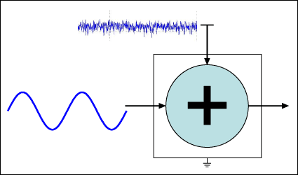
Application note 4345, "Well Grounded, Digital Is Analog" discusses grounds and power planes. We will expand on those concepts. Crosstalk and signal to noise are expressed as ratios, a proportion of good to bad. How does one improve the signal to noise of a signal? If there is a particular circuit that contributed considerable noise, we can do two things: first, reduce the noise somehow, or second, increase the amplitude of the good signal before it goes through the stage. (We will discuss the second option in application note 4993, "Reduce the Chances of Human Error: Part 2, Super Amps and Filters for Analog Interface.") Figure 1 illustrates the concept.

Figure 1. Power-supply noise or ground being added to the signal.
We should review a few basic housekeeping items. What is the signal level and bandwidth coming in, and what does it need to be as it exits this stage? What is the amplitude and bandwidth of the noise (hopefully, what is its source)? Is it harmonics of a switching power supply?
We first concentrate on the power noise. We can lowpass filter the noise inserting resistors and inductors in series with the supply and capacitors to ground. How far (low) in frequency can we go? We really only want pure DC from the supply. We could use infinitely large inductors and capacitors. That's not practical, however, because the charging time constant is also infinitely long. Alternatively, we could switch the device on and grow old before it gets going. In practice, the size and cost of inductors and capacitors are the true limits. So, we want to know the frequency characteristics of the noise. If it is 50kHz and higher because of supply switching and if our wanted signal is 1kHz, then filtering may be feasible.
If we will be going into an ADC next, the anti-aliasing filter may help. (See application note 4993 for additional discussion of this topic.)
The Local Ground
We should stop thinking of "ground" as an absolute black hole that consumes everything. Application note 4292, "Where Is Ground?" helps us realize that ground is relative. A circuit on a space ship has a local reference that we call ground. That circuit functions perfectly well, even though the potential of the space ship is not the same as the earth. The British English word "earth" is usually translated "safety ground" in North America. The space ship circuit does not care about such semantic differences because the circuit only recognizes the difference between the local ground and the power-supply voltage.
Decoupling and Homogenizing
Now try to visualize the role of a power-decoupling capacitor in the space ship circuit. The capacitor (at high frequencies) makes the noise on the power voltage match that on the local ground. It "homogenizes" the noise. Homogenizing is tiny particle mixing, as in milk. Homogenization forces milk under high pressure through small holes. This breaks the milk fat particles into very small sizes that have larger surface area and are more resistant to separation and clumping.
In the electrical analogy, high-frequency noise travels both ways through the capacitor: from the power voltage to ground and from ground to the power voltage. Because we arbitrarily call ground the reference, it may seem that the ground is always "clean" of noise. To measure this, we are in fact measuring the difference between power and ground, just like the circuit on the space ship, and this makes us happy. If we only measure comparing with another reference, then we may be unhappy with the noise.
Refer back to application note 4345, "Well Grounded, Digital Is Analog," and the section titled Selecting the Capacitor for the Application where the self-resonance of capacitors is discussed. Links for the two, free SPICE self-resonance programs are found at Calibrate, Trim, and Adjust. Note that the capacitor is never a pure capacitor, but has series inductance and resistance among other features. Above the self-resonance point the capacitor acts like an inductor, however, the decoupling action continues to be effective for a while above the self-resonance point. The series resistance in wires, traces, and vias in the power-supply path acts with the inductor impedance (a small part of an ohm just above self-resonance) as a voltage-divider until the inductors' equivalent series resistance rises.
Application note 883, "Improved Power Supply Rejection for IC Linear Regulators," presents several important concepts. Look at the power-supply rejection ratios (PSRR) for the linear regulators and voltage references on their respective data sheets. Then measure the noise and its bandwidth that the power supply (typically a switching supply) exhibits. For a prototype, isolate the noise sources and determine the method of intrusion. We have seen noise radiated into a board trace act as a radio antenna, or the magnetic field extending out of a power transformer get into an inductor. Noise from external circuits and sources can also contaminate the power and ground of the power supply. A 12V automotive battery and a linear regulator comprise a relatively quiet and inexpensive tool to compare noise levels in low-voltage circuits.
Application note 883 suggests several ways to filter power to remove noise. The first method uses one or more cascades of external RC filters. Figure 2 shows the Spectrum Software Micro-Cap circuit simulator with a second-order cascade lowpass filter and its frequency response. A link to the free Microcap evaluation version can be found at Calibrate, Trim, and Adjust.

Figure 2. The frequency response of a second-order RC filter.
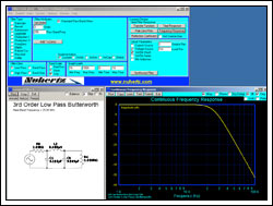
Application note 883's second suggestion for filtering power to remove noise is an LC filter. This approach proposes filters with equal input and output termination resistors. This design causes a large power loss to dampen the filter. The math to do unequal terminations is beyond the scope of that application note. Figure 3 uses a free filter design program to produce the required unequal terminations. A link to the Filter Free program from Nuhertz Technologies is found at Calibrate, Trim, and Adjust.

Figure 3. A filter design program allowing unequal termination resistors.
This program allows a practical filter to be easily realized. An RC and an LC filter can be cascaded and simulated in the Micro-Cap program.
The third suggestion of application note 883 is to cascade two linear regulators. The second regulator could be a very low-noise voltage reference for light loads.
Application note 3656, "Single Transistor Reduces LDO Noise by 46dB," uses a lowpass RC filter to reduce noise. Application notes 3657, "Ultra-Low-Noise LDO Achieves 6nV/√Hz Noise Performance," and 2027, "Simple Methods Reduce Input Ripple for All Charge Pumps," both utilize LC filters.
Scope Probe Ground
Even a 3in ground clip can be an issue. If the ground clip has to be changed to another ground point between measurements, the results may not be the same. Therefore, first go look in the lab drawer for the little plastic bag that came with the scope probe. In the bag are strange-looking pieces of metal to make short ground connections that are placed on the probe after the insulating cover is removed. Tektronix® has articles on scope probes at www.tek.com/learning/probes-tutorial/.
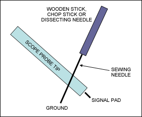
Here is a trick we use at Analog Devices. Make a tool by pressing a sewing needle into the end of a piece of wood (Figure 4).

Figure 4. A simple tool for inserting a ground onto a scope probe.
Remove the ground lead and alligator clip. Remove the plastic probe tip cover. Most probes will then have the ground sleeve exposed. Make the ground as close as possible to the circuit. If it is difficult to get the signal pad, a second dissecting needle can be used to extend the scope probe tip.
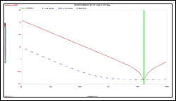
Consider an example. Look across a decoupling capacitor to see how effective it is. Ideally the capacitor should look like a short and there should be very little noise in the capacitor's frequency range. Earlier we mentioned decoupling capacitors and two SPICE programs that can help us visualize their effectiveness. Figure 5 is a screenshot of the Kemet® program. Here 0.1µF capacitors self-resonate at about 15MHz; above 15MHZ they are inductors and no longer work as decoupling capacitors.

Figure 5. The impedance and equivalent series resistance on a 0.1µF capacitor.
Margining
Margining is a technique for testing electronic parts. Some engineers compare it to the space around the text on a page; the margin on paper means that the text will be on the page, even if there is a tolerance in the text-to-paper alignment. The margining technique has existed for a long time, but lately has gained popularity in the computer field. Some engineers found that increasing the power-supply voltage would allow some circuits to run faster, that is if they didn't overheat and fail. Manufacturers have started binning or sorting their boards into speed groups, selling the faster boards at a premium price. As things evolved, manufacturers also learned that by changing the power-supply voltages, the reliability of a board could be assessed. Boards running poorly near the margins indicated tolerance build up, which presented more opportunities for failure. Consequently, margining has become a common final-test procedure, that is, repeating tests at slightly higher and lower power voltages.
Application Note 4149, "How to Add Margining Capability to a DC-DC Converter," details a method to add margining using current DACs. Digital potentiometers are also useful for remote power-voltage adjustment and margining. See the following application notes for more information on this topic:
- 4564, "Add Precise Output Adjustment to Low-Voltage Supplies"
- 818, "Digital Adjustment of DC-DC Converter Output Voltage in Portable Applications"
- 3484,"Upgrading from Mechanical Potentiometers to Digital Pots"
Power Supplies
Power supplies are always critical. Understanding switching supplies and the range of available designs will be helpful. For more information on this topic, see:
- Application note 2031, "DC-DC Converter Tutorial"
- A 323-page book with all 246 power circuits (see above item) including schematics and parts lists(PDF)
- Application note 4596, "Improve Two-Phase Buck Converter Performance with a Coupled-Choke Topology" (this reduces ripple)
- Application note 2391, "Dual Voltage Tracking Circuit for I/O, Microprocessor, and DSP Core Voltages."
Analog Devices's EE-Sim® tool generates an interactive schematic that features a highly efficient simulation engine. The EE-Sim sofware contains 25 switched-capacitor filter programs and 25 power circuits (as of February 2011) and more continue to be added.
We cannot leave the topic of power supplies without a word on thermal considerations. See application notes 4083, "Thermal Characterization of IC Packages," and 4456, "Understand Thermal Derating Aspects of PWM ICs to Ensure the Best System Performance."
Noisy Switching Power Supplies
Switching power supplies have received a bad reputation for being noisy. Some criticism is deserved, and some is not. Many times the same IC power supply in an experienced engineer's hands will have no problem. Many managers mistakenly relegate power supplies to the new engineer because they are "easy" to design in. "Just wire the IC like the data sheet says," and it should work. We have seen design nightmares, but then the heavy noise is suddenly fixed when an experienced designer rotates a component just one-eighth inch and thereby fattens a ground trace. More often it takes further work to remove the noise, but the solution is all rooted in the knowledge of the currents flowing around the chip and especially in the grounds.
The following application notes will help any engineer who lacks exposure to analog design:
- 3645, "Correct Board Layout Lowers EMI of Switchmode Converters"
- 2997, "Basic Switching-Regulator-Layout Techniques"
- 1897, "Building a DC-DC Power Supply that Works"
- 716, "Proper Layout and Component Selection Controls EMI"
- 1167, "Practical aspects of EMI protection"
- 735, "Layout Considerations for Non-Isolated DC-DC Converters"
Special Challenges of Switching Supplies, Audio, and Radio
Many times it is helpful to look at extremely difficult examples to understand the concepts. Switching power supplies, audio, and radios are such difficult examples. Power supplies have issues because of the high currents and fast switching rise and fall times. Audio has signal-to-noise issues because human hearing has wide dynamic range. Radios have to extract signals from the noise, many times the wireless part losses are more than 100dB.
Two Application notes emphasize these issues: 3630, "Power Supply and Ground Design for a WiFi® Transceiver," and 4079, "Minimize Noise in Audio Channels with Smart PCB Layout."
Star Ground and Control of Return Current
We now return to application note 4345, "Well Grounded, Digital Is Analog." That article provides some comic relief to demonstrate simple, but effective, star ground and return current control.
Conclusion
Engineers would certainly be happy if we had a cookie-cutter method to fix every noise issue. But engineering design is not that easy. Even experienced analog designers will plan on at least three PC Board layouts, and even then massage the layout before going into a pilot production run. We hope that these techniques will help direct thinking towards ways to fix the power and ground issues during the design process.


