LT1610 Micropower Step-Up DC/DC Converter Runs at 1.7MHz
Introduction
When designing portable electronics, be it a pager, handheld computer or cell phone, “footprint” is one of the most important specifications of any component. Most such products use at least one DC/DC converter to generate regulated voltages from a battery. The LT1610, a micropower DC/DC converter IC, addresses the issue of footprint in several ways. First, the switching frequency is 1.7MHz, allowing the use of small, inexpensive, minimal-height inductors and capacitors. Second, the frequency-compensation components have been integrated, eliminating the requirement for an external RC network in most applications. Finally, the device comes in LTC’s 8-lead MSOP package, one-half the size of the 8-lead SO package.
The LT1610’s input voltage ranges from 1V to 8V, and the 30V, 300mA switch allows several different configurations, such as boost, SEPIC and flyback, to be successfully implemented. Output voltage can be up to 28V in boost mode. Operating quiescent current is 50µA unloaded; grounding the shutdown pin reduces the current to 0.5µA. The device can generate 3V at 30mA from a single (1V) cell, or 5V at 100mA from two cells (2V). Configured as a Li-Ion cell to 3.3V SEPIC converter, the LT1610 can deliver 100mA. In boost mode, efficiency ranges from 60% at a 100µA load to 83% at full load.
Single-Cell to 3V DC/DC Converter
A 1V to 3V boost converter is shown in Figure 1. The specified components take up very little board space. The 4.7µ H Murata inductor specified measures 2.5mm by 3.2mm and is only 2mm high. The 22µF AVX “A” case tantalum capacitors measure 1.6mm by 3.2mm and are 1.6mm tall. Circuit efficiency, which reaches 77%, is detailed in Figure 2. Transient response to a 1mA to 31mA load step is pictured in Figure 3. The device features Burst Mode operation at light loads. This can be seen at a load of 1mA. When the load is increased to 31mA, the device shifts to constant-frequency switching and peak switch current is controlled to achieve output regulation.
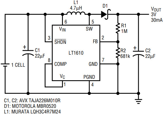
Figure 1. Single cell to 3V converter delivers 30mA.
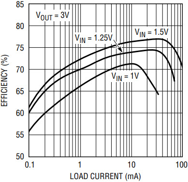
Figure 2. Single-cell converter efficiency reaches 77%.
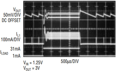
Figure 3. Transient load response of single-cell converter, load stepped from 1mA to 31mA.
2-Cell to 5V DC/DC Converter
By simply changing the feedback resistor values, the LT1610 can generate 5V. Figure 4’s circuit generates 5V at a load of up to 100mA from a 2-cell input. Figure 5’s graph shows efficiency of the circuit, which reaches 83%. This circuit is also suitable for 3.3V to 5V conversion, supplying over 200mA.
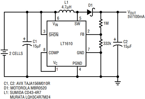
Figure 4. 2 cell to 5V converter delivers 100mA at 2V input.
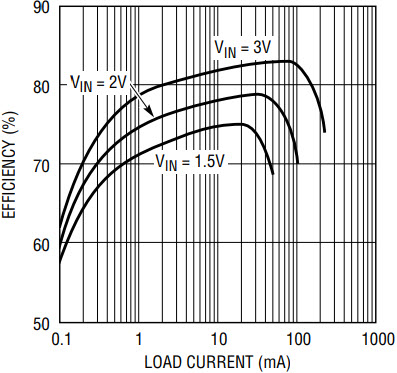
Figure 5. 2-cell converter efficiency reaches 83%.
Li-Ion to 3.3V SEPIC Converter
Figure 6 employs the SEPIC (single ended primary inductance converter) topology to provide a regulated 3.3V output from an input that can range above or below the output voltage. Although the circuit requires two inductors and a ceramic coupling capacitor, the total footprint of this solution is still attractive compared with alternative methods of generating 3.3V, such as a boost converter followed by a linear regulator. The circuit can supply up to 100mA. Efficiency, while lower than that of a standard boost converter, reaches approximately 73%. Unlike a boost converter, this topology provides input-to-output isolation. The output is completely disconnected from the battery in shutdown mode, preventing inadvertent battery discharge through the load. The LT1610’s sub-µA shutdown current reduces standby losses, increasing battery life.
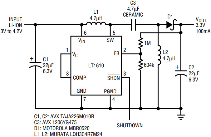
Figure 6. Li-Ion to 3.3V SEPIC converter delivers 100mA.


