Introduction of LTpowerPlanner Program – A System Level Power Architecture Design Tool
Introduction of LTpowerPlanner Program – A System Level Power Architecture Design Tool
著者
Henry Zhang
2016年02月19日
Modern electronics systems have an increasing level of complexity. There can be a large number of power rails and supply solutions on a system board. Before choosing or designing each individual power supply, the system hardware engineer first needs to understand the system power needs and then architect the system power tree accordingly to optimize the power management system efficiency, size and cost.
The LTpowerPlanner® program is a system-level block diagram tool to help system designers to plan, design and optimize a power management system. It provides an intuitive graphic user interface (GUI) to greatly simplify system-level design tasks.
The LTpowerPlanner tool helps users to:
- Draw a “power tree” type system block diagram
- Calculate/estimate total system input power, output power, power loss, efficiency and PCB size
- Compare different power architectures for a system-level optimization
- Interface with the LTpowerCAD® and LTspice® tools
- Intuitively document and present the system solution
The LTpowerPlanner III design tool runs on Microsoft Windows PCs. It can be found inside the “LTC Toolbox” of the LTpowerCAD GUI program, which is available for free download at www.linear.com/LTpowerCAD.
To get started, here are three basic steps to use the LTpowerPlanner design tool.
Step 1. Drawing a System Power Tree

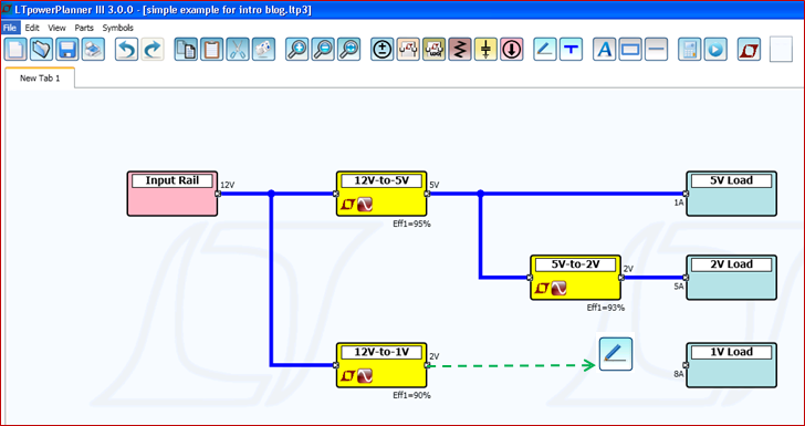
Figure 1 above shows an example of using the LTpowerPlanner tool to draw a simple system power tree. There are three types of key components in a power tree: input power source, power supply converter and load device. The power source component only has the output terminal and the load component only has the input terminal. As to each converter component, the left side terminal is a power input terminal and the right side terminal is a power output terminal. The converter component can have multiple output rails to represent a multi-channel power supply. Similarly, the load component can have multiple input rails.
The user can place these components first, then connect the components with power wires from left to right, which is the default current/power flow direction.
Step 2. Updating Component Parameters
The LTpowerPlanner parts are generic components. The user can click on each component to update its key power parameters in its “Properties” window, such as input voltage range, output voltage, maximum load current, etc. The user also needs to enter the expected efficiency and estimated size for each power converter component for a system calculation.


Step 3. Running System Calculation
After the user completes the power tree and updates all key parameters, he/she can run a system calculation. Based on the entered parameters for each component, the program calculates and displays following values in its on-screen “Summary Report:” total system input power, output power, power loss, efficiency and the sum of the converter areas. As shown in Figure 3 below, each component terminal also shows its input or output voltage and current. Each converter’s efficiency and power loss are displayed under the converter. Each load and power source’s power level is shown as well. This GUI interface really provides a very intuitive display of the system power tree to engineers.


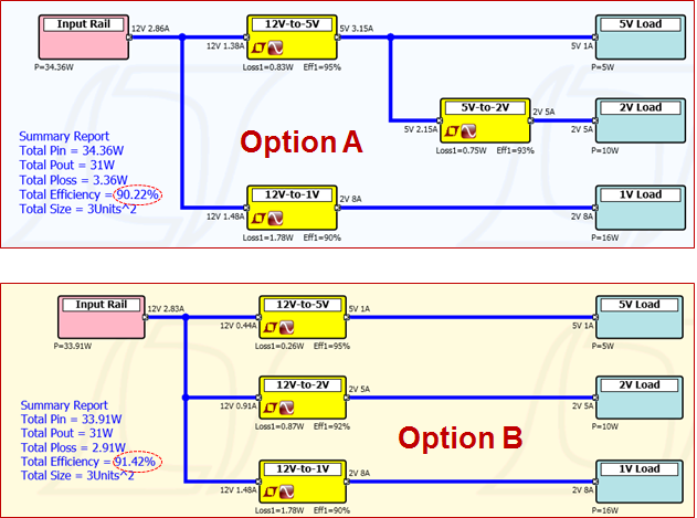
Furthermore, the LTpowerPlanner tool can be used to compare different power architectures to achieve an optimum system solution. Figure 4 below shows a simple example of comparing two slightly different power trees in option A and B. In this case, LTpowerPlanner tool shows that a small architectural change can quickly improve the system efficiency.

The LTpowerPlanner tool can be used to draw much more complicated systems. An example is given in Figure 5. There are multi-output power converters and multi-input loads shown in this example. Multiple output terminals with the same voltage can be paralleled with current sharing as well. There are also resistive components availalbe to represent voltage drop and power loss. Please see the LTpowerPlanner User Guide for details of all the advanced features and functions.


Although the LTpowerPlanner program is a generic system tool, the user can also link a power converter to existing design and simulation files generated by the powerful LTpowerCAD supply design tool and the LTspice circuit simulation tool. To do so, in the converter “Properties” window, users need to link the converter to the specific files on their PC disk. After the links are established, users can directly open the linked LTpowerCAD design file or LTspice simulation file from LTpowerPlanner GUI. This feature provides a convenient and systematic way to organize all the design files for a power management system.


In summary, the LTpowerPlanner III design tool can help system engineers to design and optimize a power management system in a very effective and intuitive way. Based on user’s inputs, the tool calculates total input power, output power, power loss, efficiency and size of the system. System designers can use this tool to draw, design, compare and optimize the power system tree. This tool also provides a nice way to document and present the system power architecture.
著者について
この記事に関して
資料
ユーザ・ガイド


