lwIPを組み込みアプリケーションで利用する方法、軽量型のTCP/IPの活用が可能に
概要
TCP/IP(Transmission Control Protocol /Internet Protocol)は、イーサネット用の通信インターフェースとしてLANやWANで広く使用されます。本稿で取り上げるlwIP(Lightweight TCP/IP)は、その軽量版として開発されたオープンソースのソフトウェアです。組み込みシステムでの利用に向けて、lwIPは必要なRAMの容量を抑えられるようTCP/IPのプロトコルをスケールダウンする形で実装されています。本稿では、このlwIPを組み込みアプリケーションで利用するためのガイドを提供します。本稿を参考にすることにより、開発プロセスの効率を改善し、時間と労力を節約することが可能になります。
はじめに
上述したとおり、lwIPはTCP/IPの軽量版プロトコル・スタックです。組み込みシステムでの利用に向けて、必要なRAMの容量を最小限に抑えられるようコンパクトに実装されています。lwIPでは、以下に示す3種のAPI(Application Programming Interface)が提供されています。
- 低レベルのraw API
- より高いレベルのnetconn API
- BSDスタイルのsocket API
これらのうち、本稿ではraw APIを使用する例を取り上げます。raw APIは、下層に当たるOSが存在しない場合でも動作するよう、イベント駆動型のAPIとして設計されています。これを使用するアプリケーションには、コア・イベントによってトリガされるコールバック関数を実装することになります。
raw APIは、socket APIと比べれば複雑です。ただ、オーバーヘッドが小さく、socket APIを使用する場合よりも、はるかに高いスループットが得られます。
本稿では、アナログ・デバイセズのマイクロコントローラ「MAX32570」を例にとり、lwIPを利用する形で実装された様々なサンプルを紹介することにします。最初のセクションでは、PCからデバイスに対してpingを実行するサンプルを示します。続くセクションでは、TCPソケットを使用するEchoサーバ(TCPEchoサーバ)のサンプルについて説明します。その初歩的なサンプルは、TCP接続のテストに役立ちます。
アナログ・デバイセズは、マイクロコントローラ(MAXシリーズ)向けのソフトウェア開発キット(SDK:Software Development Kit)として「MaximSDK」を提供しています。同SDKには、MAX32xxx用のファームウェアを開発するために必要なソフトウェアやツールが含まれています。図1に示したのは、MaximSDKのフォルダ構造です。ご覧のように、MaximSDK\Libraries\lwIPフォルダにはlwIPのライブラリ・ファイルが含まれています。

図1. MaximSDKのフォルダ構造。lwIPのライブラリ・ファイルが含まれています。
lwIPフォルダには、以下に示す複数のサブフォルダが存在します。
- apiフォルダ(netconn APIとsocket API)
- coreフォルダ(tcp.cやip.cなど、lwIPのコア・ファイル)
- netifフォルダ(ネットワーク・インターフェースのファイル)
- includeフォルダ(lwIPのすべてのincludeファイル)
- Maximフォルダ(アナログ・デバイセズのマイクロコントローラ用にカスタマイズされたMAC ドライバ)
lwIPのアーキテクチャは、TCP/IPのモデル構造に基づいています。TCP/IPのプロトコルは、複数の階層、複数の異なるプロトコルを組み合わせた形で構成されます。一般的には、図2に示す4階層のシステムだと見なされます。
図2. TCP/IPの階層構造
lwIPのプロジェクトには、lwipopts.hという設定(コンフィギュレーション)ファイルと、opt.hというデフォルトの設定ファイルが必ず含まれます。opt.hには、スタックのデフォルトの設定とそのモジュールの設定が定義されています。一方のlwipopts.hは、ユーザが独自にそれらの設定を行うためのものです。但し、lwipopts.hにはlwIPで設定可能なすべてのオプションが含まれているわけではありません。lwipopts.hで定義されていない設定については、opt.hで定義されているデフォルトの設定が適用されます。
同様に、lwIPのライブラリには、lwipcfg.hというアプリケーション固有のヘッダ・ファイルが用意されています。このファイルには、コントローラのIPアドレス、ゲートウェイのアドレス、ネットマスク・アドレス、MACアドレスを定義する必要があります(図3)。

図3. lwipcfg.hの記述例
lwIPと、その基盤になるハードウェア・ドライバの間の接続を確立するためには、プラットフォーム固有のアダプテーション層が必要です。例えば、マイクロコントローラ用のlwIPのスタックを実装する際には、そのスタックとマイクロコントローラのイーサネット用MACドライバを結び付けるカスタムのドライバが必要になります。そのドライバには、以下の機能を用意しなければなりません。
- 初期化機能:マイクロコントローラに固有のMACドライバを初期化します。
- 送信機能:TCPのスタックから受信したデータを、その後の送信に向けてイーサネット用MAC ドライバに転送します。
- 受信機能:イーサネット用MACドライバから受信したパケットをTCP スタックに向けてフォワードします。
アナログ・デバイセズのマイクロコントローラについては、カスタマイズされたドライバがMaximSDK\Libraries\lwIP\Maxim\mxc_eth.cとして用意されています。このドライバは、ペリフェラル・ライブラリに対するEMAC(マイクロコントローラ独自のイーサネット用MAC)のラッパーの役割を果たします。EMACのペリフェラル・ライブラリは、C:\MaximSDK\ Libraries\PeriphDrivers\Source\EMACとして用意されています。
pingのサンプル
pingコマンドは、ネットワークのトラブルシューティングにも使われるシンプルなツールです。このコマンドを実行すると、特定のIPアドレスを対象として信号が送信され、その応答を待つことになります。これは、ICMP(Internet Control Message Protocol)を使用してエコーを要求する処理に相当します。pingの送り先は、その要求を受信すると、エコー応答のパケットを返送します。このセクションでは、WindowsベースのPCからマイクロコントローラに対してpingコマンドを実行する例を示します。つまり、基本的なpingのテストを実行してその接続を確認するということです。また、マイクロコントローラのpingモジュールを使用してPCと通信する方法も示すことにします。
Windowsのpingユーティリティは、以下のように動作します。
- 4つのデータ・パケットをマイクロコントローラに送信して応答を待ちます。
- マイクロコントローラは、それらのデータ・パケットをPCに対する応答として送り返します。この処理はエコー応答と呼ばれます。
pingのテストを実行する手順は、以下のようになります。
- イーサネット・ケーブルを使用して、マイクロコントローラの評価用キットとPC を接続します。
- コマンド・プロンプトを開き、「ping[ マイクロコントローラのIP アドレス]」と入力して< Enter >キーを押します。
上記のようにpingコマンドを実行すると、コマンド・プロンプトに図4に示すような応答が表示されるはずです。これにより、PCとマイクロコントローラが正しく接続されていることがわかります。
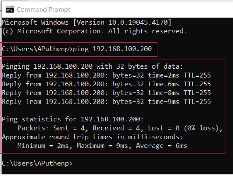
図4. コマンド・プロンプトに表示されたpingの実行結果
マイクロコントローラ側でpingを実行する
MaximSDKには、MAX32570用のpingのサンプルとしてC:\MaximSDK\Examples\MAX32570\lwIP_Pingが用意されています。これに関するガイダンスを以下に示します。
- マイクロコントローラのIPアドレスは、lwipcfg.hを使用して設定します。マイクロコントローラとPC のIP アドレスは、同じシリーズ(series)でなければなりません。
- PCのIPアドレスは、ゲートウェイ・アドレスとしてマイクロコントローラのlwipcfg.h 中に記述する必要があります。
- PCとMAX32570の評価用キットをイーサネット・ケーブルで接続します。
- pingのサンプル・コードを実行します。
- Eclipse(ソフトウェア開発環境)上で[Window]→[Show view]→[Terminal]を選択し、シリアル・ターミナルを起動します。ping の処理が成功した場合には、同ターミナルに図5 のような結果が表示されます。
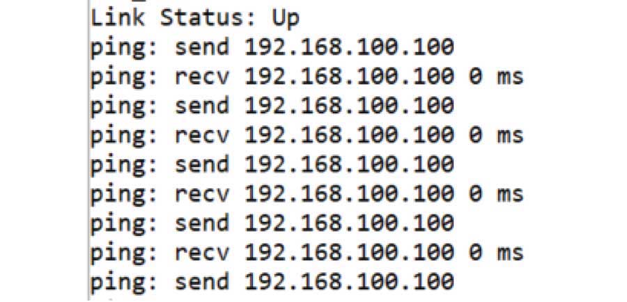
図5. シリアル・ターミナルに表示されたpingの実行結果
なお、コマンド・プロンプトにはpingの統計的な実行結果(応答時間)しか表示されません。実際に送信されたデータの内容を確認したい場合には、「Wireshark」というツールを使用するとよいでしょう。このツールは、接続されたネットワークからパケットのデータを取得します。そのデータを基に、送信元と送信先のMACアドレス、送信元と送信先のIPアドレス、通信プロトコル、送信された追加のデータといった詳細な情報を表示します。図6に示したのがWiresharkによる表示結果の例です。なお、同ツールを起動する際には、イーサネットのオプションを選択してください。
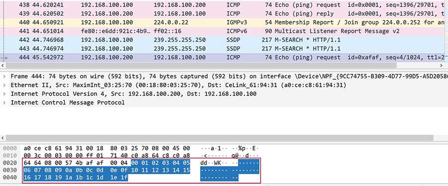
図6. Wiresharkに表示されたpingの詳細データ
図6の例では0x00、0x01、…、0x1Fというデータを送信しています。この送信データを変更したい場合にはどうすればよいのでしょうか。次の例をご覧ください。
マイクロコントローラのPingから送出されるデータの変更方法
pingで送信するデータは、ping.cというファイルで設定します。同ファイルは、pingの送信側モジュールに当たります。送信データのサイズは、同ファイル中のPING_DATA_SIZEで設定します。図7の例ではデータ・サイズが32バイトに設定されています。

図7. 送信データのサイズの設定
送信データは、同ファイルの図8の部分で定義しています。ここまでの例では、追加のデータ・バッファに0x00、0x01、0x02、…、0x1Fというデータを設定していました。

図8. pingで送信するデータの設定(変更前)
アプリケーションの事情に応じてこのデータを変更したい場合には、このデータ・バッファの部分を編集します。図9の例では、32バイトのデータを0x01、0x01、…、0x01に変更しています。

図9. pingで送信するデータの設定(変更後)
図9のように変更したping .cを使用した場合、Wiresharkに表示される結果は図10のようになります。新しいパラメータによってデータが更新されていることがわかります。

図10. 図9のファイルを使用した場合のWiresharkの表示結果
TCP Echoサーバの使用方法
先述したように、pingのサンプルではICMPを使用して対象とするシステムの応答を確認します。その際には、意図した送信先に対し、ネットワークを介してエコー要求が送信されます。その際に使われるのはデフォルトのデータです。その要求を受け取った送信先は、エコー応答を返送します。
あるデバイスから別のデバイスに対してカスタマイズされたデータを送信したい場合、TCPを使用することでそのデータの転送を実現できます。Echoのサービスは標準的なTCPの機能です。そのサービスの主な用途は、到達可能性を確認してルーティングの問題を特定することです。このサービスにおいて、サーバとクライアントの関係はTCPを使用することで確立されます。サーバはクライアントからのメッセージを受信したら、それと同じメッセージを送り返します。
MaximSDKを利用する場合、lwIP TCPのソース・ファイルを確認すれば、lwIPのライブラリにおけるTCPの関数の使用方法を把握できます。その例では、マイクロコントローラがTCPサーバとして機能し、クライアントからの要求を待ちます。そして、クライアントから送信されたデータはエコー・バックされます。TCP Echoサーバのサンプルとしては、tcpecho_raw.cというアプリケーションのソース・ファイルが提供されています。
TCP Echoサーバは、以下に示す手順で動作します。
- ソケットを生成します。
- アドバタイズされたポート番号にソケットをバインドします。
- バインドが完了したら、サーバは接続/受信のためのリッスンの処理を開始します。
- 接続が要求されたら、サーバはクライアント・マシンからの要求を受け付けます。
- 続いて、サーバはクライアントからのデータを受信します。
- 最後に、サーバは同じデータを送り返します。
図11は、main関数に含まれているコード(一部抜粋)を示したものです。これを見れば、ファームウェアの概要を把握できます。ここで、config_emac関数はEMACを初期化する役割を果たします。MXC_ETH_Init関数はlwIPのスタックを初期化するために使用されます。
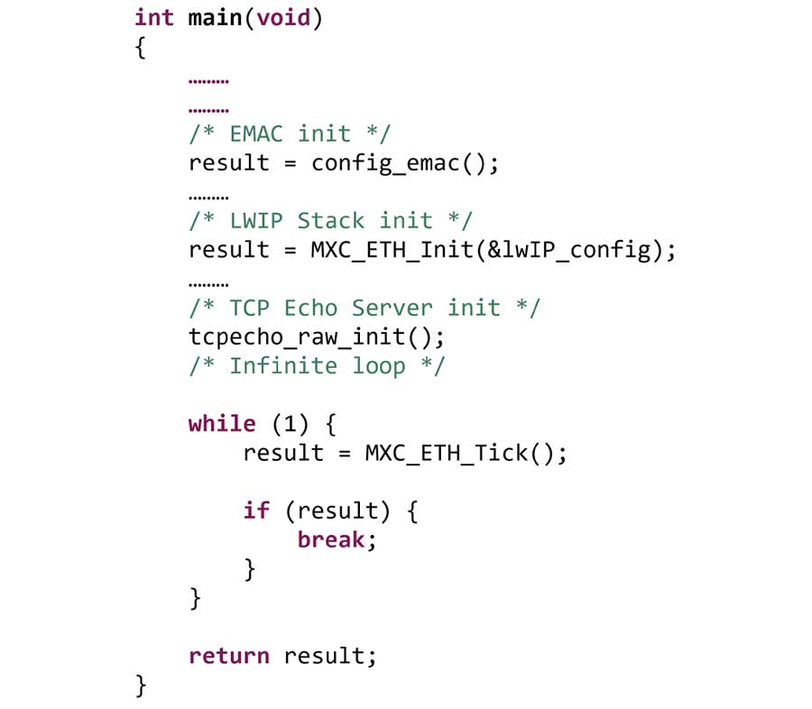
図11. ファームウェアのmain関数(一部抜粋)
EMACとlwIPのスタックを初期化したら、tcpecho_raw_init関数によってTCP Echoサーバを初期化します(図12)。
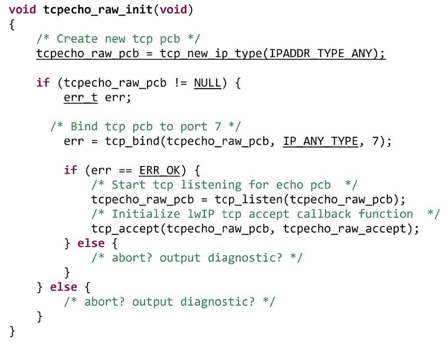
図12. TCP Echoサーバの初期化処理(tcpecho_raw_init関数)
TCP Echoサーバの初期化処理としては、まず新たなソケットが生成されます。続いて、割り当てられたIPアドレスとポート番号がそのソケットにバインドされます。バインドが完了したら、サーバはリモート・クライアントからの接続要求をリッスンします。
このTCP Echoサーバのサンプルを実行するには、PC用のクライアント・ユーティリティである「EchoTool」を使用します。その際には、echotool.exeというファイルをCドライブに保存し、コマンド・プロンプトをCドライブで起動する必要があります。このユーティリティをクライアント・モードで実行すると、サーバにデータが送信されます。その結果として、図13に示すような応答が返ってくるかどうかを確認します。サーバのデモを実行する場合、このツールは必ずクライアント・モードで使用してください。
TCP Echoサーバのサンプルの実行方法
続いて、TCP Echoサーバのサンプルの実行方法を示します。その手順は以下のようになります。
- すべての接続が正しく行われていることを確認します。
- Eclipseを使用してサンプル・コードをビルドします。
- ビルド済みのコードをデバッグ・モードで実行します。
- リモートのPC上でコマンド・プロンプトを起動します。
- コマンド・プロンプトに以下のように入力します。
-
"C:\>echotool IP_address /p tcp /r 7 /n 15 /t 2 /d LwIP TCP echo server Example"
ここで、各引数やオプションの意味は以下のとおりです。
    IP_address: 実際のボードのIPアドレス(スタティックなIPアドレスは192.168.100.200)
    /p tcp:プロトコルはTCP
    /r:TCP Echoサーバの実際のリモート・ポート(Echoポート)
    /n:エコー要求の数
    /t:接続タイムアウトの秒数
    /d: 送信するメッセージ(この例では「LwIP TCP echo server Example」)。
-
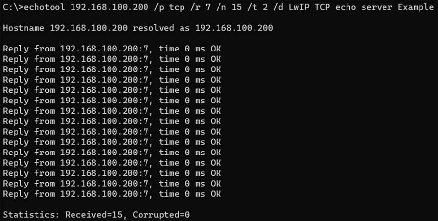
図13. TCP Echoサーバの応答
TCPを利用するネットワークを介して送信されたデータは、Wiresharkを使用することによって確認できます(図14)。この例では、コマンド・プロンプトを介して「LwIP TCP echo server Example」というデータを送信しました。それと同じデータがWiresharkに表示されていることがわかります。
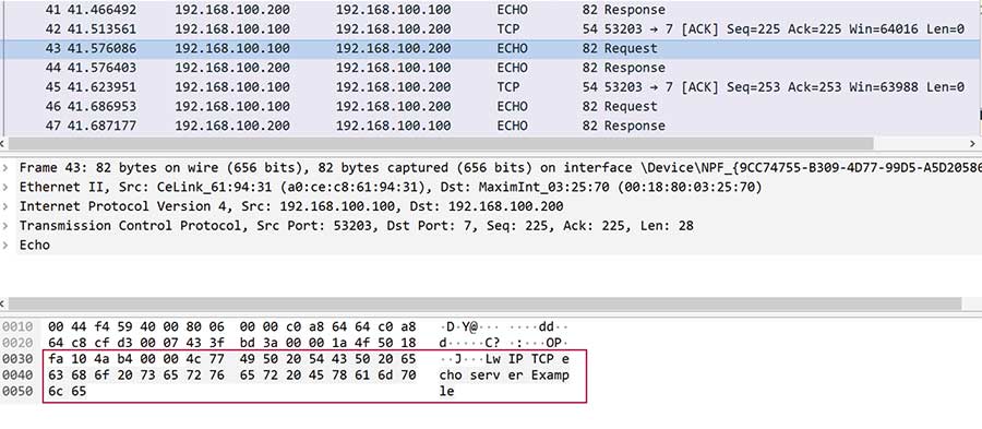
図14. Wiresharkに表示されたTCP Echoサーバの応答
まとめ
本稿では、lwIPの機能や使い方について解説しました。このlwIPに、ICMPをベースとするpingツールとTCPを組み合わせれば、ネットワークの診断を実行できます。また、データ転送についても様々な利用方法が考えられるでしょう。アナログ・デバイセズのMAX32570とMaximSDKを堅牢な基盤として利用すれば、lwIPを実装して信頼性の高い通信システムを構築することができます。すなわち、シームレスな接続を実現し、データ・インテグリティを確保することが可能です。また、本稿で紹介したサンプルは、ネットワークで問題が発生した際のトラブルシューティングにも役立つでしょう。


