Fast Rate Li-Ion Battery Charger
Introduction
The recent trend in notebook computers has been toward increasing battery operating time and faster processor speeds. These two requirements, in conjunction with a need for faster battery recharging (1–2 hours) have placed a strain on battery charging circuits and wall adapters. A typical notebook computer system configuration is shown in Figure 1.
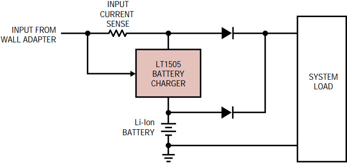
Figure 1. Typical notebook computer power supply.
Wall adapters are typically AC/DC converters with a 20V output at 3A–4A of load current. When a notebook computer is running, all of the available current from the wall adapter may be consumed by the system, with no power left for charging the battery. However, as soon as the system’s power requirements drop below the wall adapter’s current limit, the battery charging can resume. In order to recharge the battery in the shortest time possible, the recharging should start as soon as there is any current left over from the system. The ideal situation is when the sum of battery charging current and the system current is just below the wall adapter’s current limit:

where IIN_MAX is the wall adapter current limit, ISYS is the system load current and ICHARGER is the battery charger current.
To achieve this objective, it is necessary to adjust the battery charger current so that the sum of the two currents is just below the maximum available input current, IIN_MAX. The LT1505 incorporates a patented battery charger input current limiting function along with other functions necessary to provide a complete, single-chip battery charging circuit solution.
LT1505 Features
The LT1505 is a constant-current (CC), constant-voltage (CV) current mode switching battery charger circuit with the following features:
- 0.5% voltage reference
- 5% output current regulation
- Output voltage is preset for 3 or 4 Li-Ion cells (12.3V, 12.6V, 16.4V and 16.8V)
- Output voltage is programmable from 1V to 21V
- Low VIN-to-VOUT operation (dropout <0.5V)
- Programmable AC wall adapter current limiting
- Programmable peak battery charging current
- Battery drain <10µA in shutdown
- 94% efficiency
Circuit Description
The LT1505 is a synchronous buck converter using N-channel MOSFETs. The LT1505 operates at 200kHz and can be synchronized to an external clock with a frequency higher than 240kHz. The LT1505 IC has an undervoltage lockout circuit that detects the presence of an input power source and enables the battery charging. Once the undervoltage lockout has been exceeded, the PWM will start running and the input MOSFET M3 is turned ON, thus reducing the voltage drop across its internal body diode DBODY (see Figure 2).
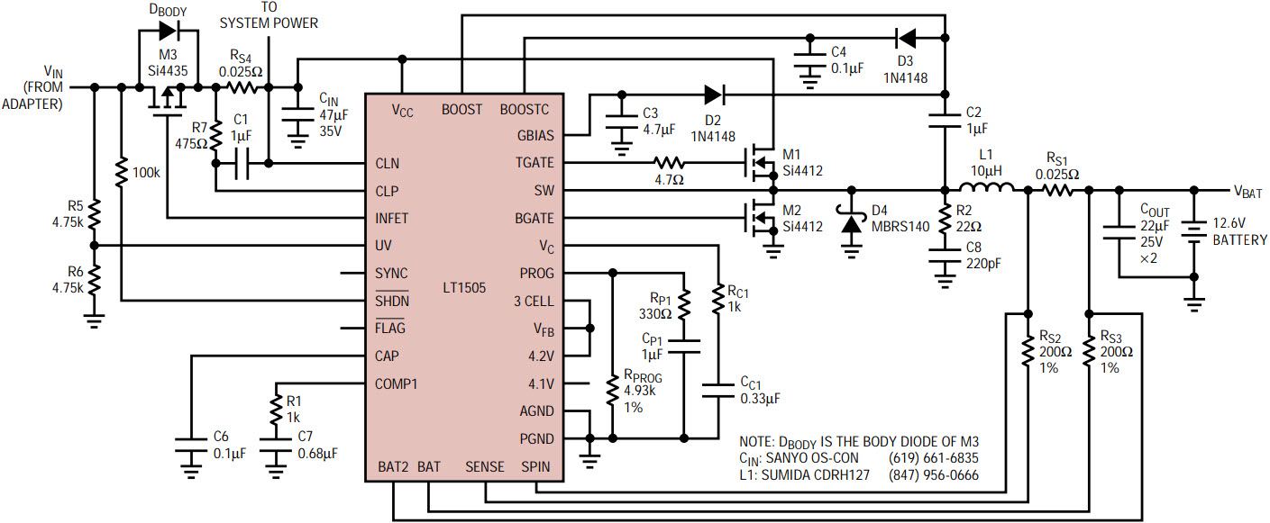
Figure 2. 4A Li-Ion battery charger.
The LT1505 monitors the current from the wall adapter and controls the battery charger current. For example, if a 3A, 20V wall adapter is used along with a 12.6V Li-Ion battery pack, the peak battery charging current, when the system is off, can be set to:

where IBATT MAX is the maximum battery charging current when the system is idle, η is the efficiency of battery charger, VIN is the wall adapter output voltage and VBATT is the battery charging voltage.
Assuming an efficiency of 90%, the above example could provide battery charging current in excess of 4A. The LT1505 will reduce the battery charging current as soon as the system current exceeds (IIN_MAX – ICHARGER). For example, if a 20V, 3A wall adapter is used and the system draws 2A from the adapter, the available current for charging the battery will be ICHARGER = 1A. The resulting battery charging current IBATT will be:

or

The input current from the wall adapter passes through a current sense resistor, RS4. One part of the input current goes to the system load and the remaining part goes to the LT1505 battery charger. The voltage drop across RS4 is monitored by a current comparator with a 90mV threshold. Once the threshold of 90mV is reached, the LT1505 will reduce the programmed battery charging current so that the peak input current does not exceed the preset limit. Thus, the maximum input current (IIN_MAX) will be:

where ISYSTEM is the system load current, ICHARGER is the LT1505 battery charger current and RS4 is the current sense resistor. With the resistor value of 0.025Ω in Figure 2, the input current limit IIN_MAX will be set to 3.6A.
The battery charging current limit is set by RPROG, RS1 and RS2 and is:

where VPROG is the reference voltage of 2.465V. The values in Figure 2 have been selected for a current limit (IBAT_MAX) of 4A. Changing RS1 to 0.050Ω will set the IBAT_MAX to 2A.
Also, the peak battery charging current (IBAT_MAX) can be programmed by the host computer. The IBAT_MAX can be set in increments of 0.25A if RPROG is replaced by a network of resistors, as shown in Figure 3.
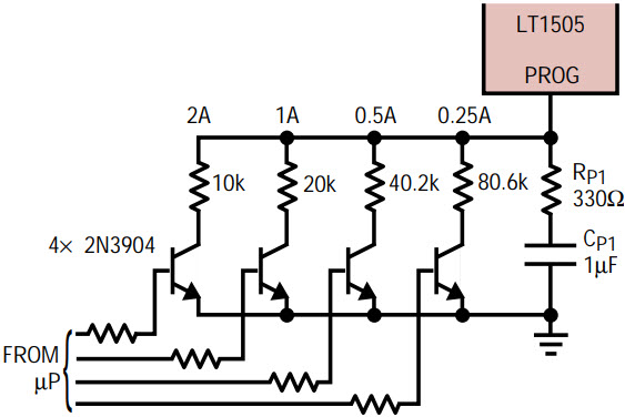
Figure 3. Programming of battery-charge current.
The battery charger in Figure 2 achieves high efficiency thanks to synchronous operation and input power FET. The efficiency is as high as 94%, as can be seen in Figure 4.
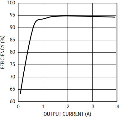
Figure 4. Efficiency of 4A, 12.6V battery charger at 20V input.
PCB Layout
When laying out the PCB, a multilayer layout with one of the inner layers as a solid ground plane is recommended. The LT1505 and low power components associated with it should be kept as close together as possible. Additionally, all power components should be kept together and next to LT1505 control circuitry. The goal is to keep all high power switching currents as localized as possible. Components that connect to the ground plane should have vias placed as close as possible to the pins connected to the ground plane. Also, power components should have larger or multiple vias connecting to the ground plane. Avoid placing the power components in such a way that input and output currents flow by the LT1505 IC. Also, to keep the component temperature rise low, use as much copper as possible. The use of polygon planes for high power nets such as the ones connecting to VIN, VCC, SW, VBAT and GND in Figure 2 will help in spreading the heat and will reduce the power dissipation in conductors and MOSFETs.
Other Applications
The LT1505 can also be used in other system topologies, such as the telecom application shown in Figure 5. The circuit in Figure 5 uses the battery to supply peak power demands. By doing so, the required peak power from the wall adapter can be much lower than the peak power required by the load. The wall adapter has to supply the average power only.
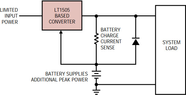
Figure 5. Typical telecom application.
Conclusion
The LT1505 is a complete, single-chip battery charger solution for today’s demanding charging requirements in high performance laptop applications. The device requires a small number of external components and provides all necessary functions for battery charging and power management. High efficiency and small size allow for easy integration with the laptop circuits. Also, by adding a simple external circuit, charging can be easily controlled by the host computer, allowing for more sophisticated charging schemes.


