Complete USB Power Manager, Li-Ion Charger and Two Buck Converters in a 4mm 4mm QFN
Complete USB Power Manager, Li-Ion Charger and Two Buck Converters in a 4mm 4mm QFN
2004年02月01日
Introduction
The LTC3455 provides a compact, easy-to-use solution that seamlessly transitions between three different input power sources: a single-cell Li-Ion battery, a USB port, and a 5V wall adapter. The device contains two synchronous buck (step-down) DC/DC converters, a USB power controller (that accurately limits USB current to 500mA or 100mA), a full-featured single-cell Li-Ion battery charger, a 200mA Hot Swap™ output, a low-battery indicator, and numerous internal protection features, all squeezed into a low-profile (0.8mm tall) 4mm × 4mm 24-Pin QFN package (Figure 1).
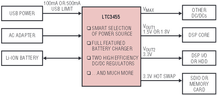
Figure 1. A complete “plug-and-play” portable power management solution in a tiny package.
The simplicity of a typical LTC3455 application is shown in Figure 2. Efficiencies for the DC/DC converters in this application are shown in Figure 3. The device handles important system startup and protection issues internally (soft-start, supply sequencing, charger thermal limiting, current limiting for all outputs, etc.) which helps minimize the number of external components. The circuit is even simpler for applications that require only a battery and USB power, without the 5V wall adapter (see note in Figure 2).
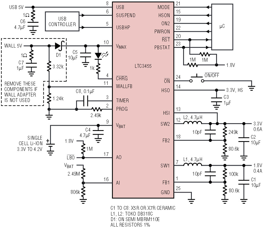
Figure 2. Typical LTC3455 application.
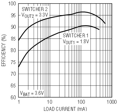
Figure 3. DC/DC converter efficiencies.
Dual High-Efficiency DC/DC Converters
The LTC3455 contains two 1.5MHz constant-frequency current-mode switching regulators that operate with efficiencies up to 96%. Switcher 1 provides up to 400mA at 1.5V/1.8V (to power a microcontroller core), and Switcher 2 provides up to 600mA at 3.3V (to power microcontroller I/O, memory and other logic circuitry). Both converters support 100% duty cycle operation (low dropout mode) when the input voltage drops very close to the output voltage, and both are capable of Burst Mode® operation for highest efficiencies at light loads (Burst Mode is pin selectable). Switcher 2 has independent ON/OFF control, but operates only when Switcher 1 is also enabled and in regulation. If both are enabled at initial power-up, Switcher 2 turns on only after Switcher 1 has reached 90% of its programmed value. This power-up delay ensures proper supply sequencing and reduces the peak battery current at startup.
Whenever external power is present, the battery charger and Switcher 1 (the core supply) are enabled. This ensures that the battery can always be charged and that the microcontroller is always alive whenever external power is available. Switcher 2 can also be set to turn on whenever external power is present. Additionally, all system power is drawn from the appropriate external source, and once the battery is fully charged, current drain on the battery is reduced to 10μA.
Make the most of USB Power
The popularity of USB (Universal Serial Bus) makes it an attractive choice for transferring data and power between devices. The ability to power a portable device via USB while charging its batteries is obviously desirable (no wall wart), but it is not necessarily an easy design problem. The power available from a single USB port (maximum 2.5W) is barely enough to support the peak power needed by many full-featured portable devices, even without adding in the power needed to quickly charge their batteries.
To further complicate matters, the USB port is not an ideal power source. Each device can draw a maximum of 500mA in high power mode (or 100mA in low power mode), but the voltage provided to the portable device can vary quite significantly. Although the USB power supply has a 5V nominal rating, when you include normal supply variations, cable losses, and transient conditions, the USB voltage showing up at the portable device is typically much lower—often falling to only 4V (even though the minimum USB specification is 4.35V). Since the USB port has a strict current limit of 500mA, this means the amount of power available to the portable device can be as low as 2W. The reduced USB voltage also presents problems when trying to fully charge a single-cell Lithium-Ion battery (that has a 4.2V final charge voltage) when the USB voltage may itself be below 4.2V.
The LTC3455’s USB power controller is specifically designed to solve these problems by offering several features that make the most of the power the USB port has to offer. The device draws USB power once the USB pin voltage reaches 3.9V, and continues drawing power until the pin voltage falls below 3.7V. If the USB pin voltage drops below 4.5V, the charge current gradually reduces (and eventually shuts off around 4.0V) to help prevent “chattering” and stability problems when using long, resistive USB cables. Figure 4 shows this reduction in charge current as USB voltage drops.
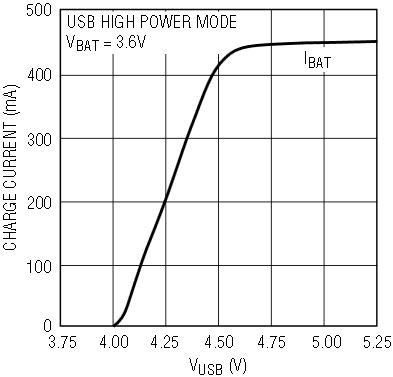
Figure 4. Charge current vs USB voltage.
The internal USB power controller also automatically throttles back the battery charge current to help keep the total system current under the strict 500mA or 100mA USB limit. The rest of the system draws whatever current it needs, but the battery charge current is reduced to try and keep the total system current below the strict USB 500mA/100mA limit. The graph in Figure 5 shows how charge current, IBAT, decreases as the current needed for the rest of the system increases (both switchers and all other external devices pull current from the VMAX pin). The total USB current, IUSB, always stays below 500mA.
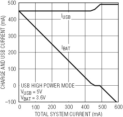
Figure 5. IBAT vs total system current.
Li-Ion Battery Charger
The battery charger is a constant-current, constant-voltage charger. In constant-current mode, the maximum charge current is set by a single external resistor. When the battery approaches the final float voltage, the charge current begins to decrease as the charger switches to constant-voltage mode. The charge cycle is terminated only by the charge timer, which is programmed using a single external capacitor. Maximum charge current is 500mA when USB powered and up to 1A when wall adapter powered. The USB power controller will automatically throttle back the charge current to help keep the total USB pin current below 500mA whenever under USB power. When the battery is below 2.8V at the start of a charge cycle, the charger goes into trickle charge mode, reducing the charge current to one-tenth of its programmed maximum value. An internal thermal limit reduces the charge current if the die temperature rises above a preset value of approximately 105°C. This feature not only protects the LTC3455 from excessive temperatures, it can also reduce charge times because it allows the user to set a higher maximum charge current—taking into account typical, instead of worse case, ambient temperatures for a given application—with the assurance that the charger will automatically reduce the current under worst-case conditions.
Hot Swap Output
A 200mA Hot Swap output is provided for powering Secure Digital (SDIO) cards, memory cards, and any other external devices that can be hot-plugged into the system. If hot-plugged directly into one of the switcher outputs, these external devices appear initially as a short and can drag down the output, causing major system problems. The HSO output can only operate when the LTC3455 is on, and is enabled using the HSON pin. For applications where hot-plugging is not needed, this output can simply be used as a 200mA load switch (controlled by the HSON pin).
Low Battery Detector/LDO
The LTC3455 contains an additional gain block (pins AI and AO) that can be used as either a low-battery indicator, or as an LDO with the addition of an external PNP or PMOS. This gain block is alive whenever the device is enabled, and turned off during shutdown to minimize battery drain. The low-battery detector will not report a low-battery condition until the LTC3455 is turned on, but this is not a problem for most applications, since the LTC3455 would power the microcontroller and all other intelligence in the system anyway. The LDO is convenient for applications needing a third output, like a 2.5V or a quiet 3V supply.
Increasing the 3.3V Output Current to 1.2A
With an internal current limit of 900mA, Switcher 2 typically provides a 3.3V, 600mA output. While this output current is sufficient for many portable devices, some applications need a 3.3V supply capable of providing more than 1A. Figure 6 shows how to implement a higher current 3.3V output using the LTC3455. By adding one tiny SOT-23 PMOS and using the gain block as an LDO, the 3.3V output now provides 1.2A of output current. Switcher 2 is programmed for an output voltage of 3.3V, and the LDO is programmed for an output voltage of 3.2V (3% lower). As long as the load current is low enough for Switcher 2 to provide, the LDO is turned off completely. This circuit is ideal for applications that need the higher 3.3V output current for only a brief time. Switcher 2 will normally provide all of the output current, and the LDO will turn on briefly to provide the higher load currents.
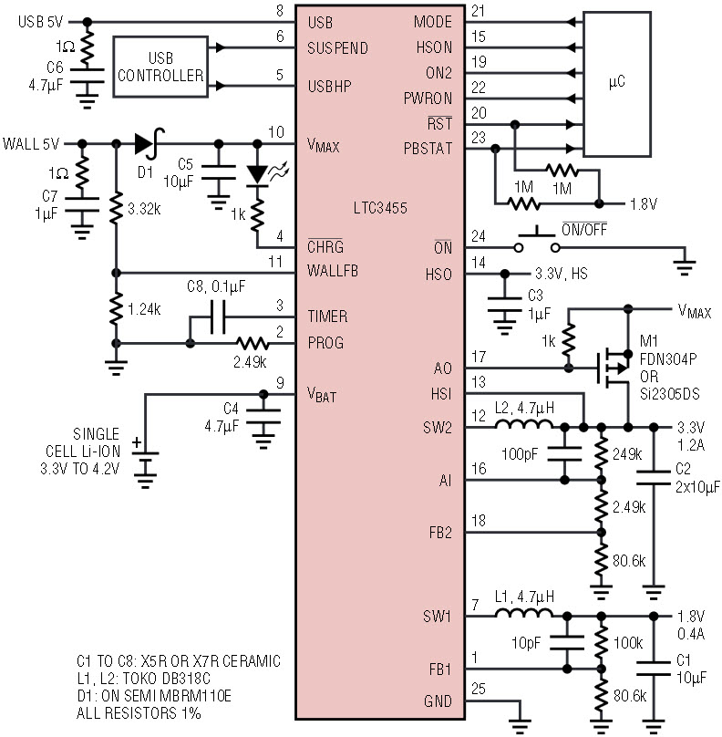
Figure 6. LTC3455 application with 3.3V output current increased to 1.2A.
When the load current exceeds what Switcher 2 can provide, the 3.3V output droops slightly and the LDO provides the additional current needed. Figure 7 shows the transient response when the 3.3V output current is stepped from 0.5A to 1.2A. More output capacitance can be added to improve the 3.3V transient response during these high current load steps.
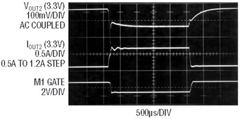
Figure 7. Load current step (0.5A to 1.2A) for 3.3V output.
USB Power Supply with Temporary Backup Power
Although designed primarily for Li-Ion powered portable applications, the LTC3455 is also a good choice for systems that are always powered by a USB supply or wall adapter. The battery charger can then be used to charge up a large capacitor or backup battery, which briefly provides power to the system after the external power has been removed. This gives the microcontroller enough time to follow proper shutdown procedures when the main power source is abruptly removed.
Figure 8 shows a standalone power supply for USB high power applications (500mA max USB current) using the LTC3455. The total system power should be kept below 1.8W to ensure clean operation even under worst-case USB conditions. With the resistor values shown, the low-battery indicator (AI and AO pins) triggers when the VMAX pin voltage drops to 4.0V, notifying the microcontroller of an impending dropout condition. The 1MΩ resistor connected between the AI and AO pins provides 150mV of hysteresis (the dropout indicator stays low until the VMAX pin rises back above 4.15V).
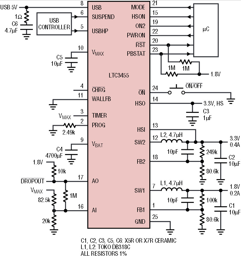
Figure 8. Standalone USB power supply with temporary backup power.
A 4700μF backup capacitor connected to the VBAT pin briefly provides power to the system after the USB supply has been removed, and also helps support transient loads that slightly exceed the USB current limit. Connecting this large capacitance to the VBAT pin has several advantages. It provides a large energy reservoir that is isolated from both the USB pin (the USB specification limits capacitance on the USB supply pin to 10μF or less) and the VMAX pin (using a very large capacitance on this pin will delay the system turn-on), and it prevents large inrush currents by using the battery charger to slowly charge this capacitor. With the TIMER pin tied to VMAX, the battery charger operates in constant-current mode (the voltage-loop and timer function are disabled), so the 4700μF capacitor is always fully charged to the available USB voltage.
Conclusion
The LTC3455 simplifies the design of portable applications. It is a complete power management solution, incorporating two step-down DC/DC converters, a USB power controller, a full-featured Li-Ion battery charger, a Hot Swap output, and a low-battery indicator—all squeezed into a tiny 4mm × 4mm QFN.


