Compensation Calculator for the MAX1864/MAX1865 xDSL Cable-Modem Power Supplies
要約
A spreadsheet calculates compensation components for a linear regulator and a buck regulator. The MAX1864 and MAX1865 xDSL cable modem power supplies are featured.
The linked Excel® spreadsheet (ZIP, 4kB) calculates compensation components based on the application requirements and components specifications. User inputs are highlighted in blue.

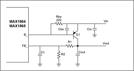
Figure 1. Linear regulator.
B2: Output voltage, Vout
B3: Maximum output current
B4: Output capacitor, Cout
B5: ESR of output capacitor
B6: Bottom feedback resistor, R2
D6: Calculated top feedback resistor, R1 (does not apply to negative regulator)
B7: Chosen top feedback resistor (next higher standard value)
B8: Current gain of pass transistor, Q1 (use maximum specification)
B9: Calculated dominant pole frequency
D9: Calculated Cbe to place second pole above unity-gain crossover frequency
B10: Calculated ESR zero frequency
D10: Calculated compensation capacitor (Cc) to cancel ESR zero. Cc < 50pF
not necessary.
B11: Calculated crossover frequency
B12: Chosen Cbe (subtract transistor Cbe, choose next lower standard value)
B13: Calculated second pole frequency

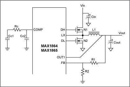
Figure 2. Buck regulator.
B16: Output voltage, Vout
B17: Maximum output current
D17: Calculated inductance assuming LIR = 0.3.
B18: Output capacitor, Cout
B19: ESR of output capacitor
D19: Calculated ESR zero frequency
B20: Maximum on-resistance of control FET, N1
B21: Chosen unity-gain crossover frequency (choose < 40kHz)
D21: Calculated compensation capacitor (Cc1) to set dominant pole
B22: Chosen compensation capacitor (standard value > D21)
B23: Calculated dominant pole frequency
D23: Calculated resistor (Rc) to cancel output pole
B24: Chosen resistor (next higher standard value)
D24: Calculated compensation capacitor (Cc2) to cancel ESR zero. Not necessary if fc < Zesr.
B25: Bottom feedback resistor, R2 (if necessary)
D25: Calculated top feedback resistor, R1


