Compact Solution for Hot Swap and Supply Monitoring in CompactPCI and PCI Express Systems
Compact Solution for Hot Swap and Supply Monitoring in CompactPCI and PCI Express Systems
2006年05月01日
Introduction
Servers that operate in critical industrial applications, such as communications and data-storage, must do so with near-zero down-time. Such high availability systems cannot be shut down to replace or upgrade circuit boards, so Hot Swap capabilities are paramount. Once a board is in the system, it is also important to continually monitor its power consumption to anticipate board failure. The LTC4245 makes it easy to satisfy both the Hot Swap and monitoring needs of high availability systems. It incorporates a quad-supply Hot Swap controller and an 8-bit ADC for board supply voltage and current monitoring. Access to supply monitoring data is via an I2C-compatible interface.
The LTC4245 is designed to be used in a CompactPCI (CPCI) Hot Swap board, where the four supplies are 12V, 5V, 3.3V, with an optional –12V. The LTC4245 can also work with one 12V and two 3.3V supplies as in a PCI Express system. Other features of the device include:
- External N-channel MOSFET switches on all four supplies allow flexible power distribution among the supplies.
- dI/dt limited inrush current control prevents supply glitches on backplane due to L • dI/dt drops.
- Each supply has a circuit breaker with a 20µs filter and a fast current limit at 3× the circuit breaker threshold, thus preventing minor load current surges from causing spurious resets.
- The four board supplies can be turned on together, in a built-in sequence or in any other sequence through the I2C interface.
- A power good input with timeout allows external supply monitors to turn off the board supplies in case of downstream faults.
- Integrated CPCI bus precharge voltage output and PCI reset signal logic saves board space in CPCI designs.
All of the above is available in a 36-pin SSOP package and a space-saving 5mm × 7mm 38-pin QFN package. The QFN package includes two GPIO pins in addition to the one on the SSOP package.
Measure Board Power Consumption with Integrated ADC
As soon as the 12V supply is available to the LTC4245, the onboard ADC starts measuring its thirteen input channels one after another. Twelve of these are the input voltage, current sense voltage, and output voltage of each supply. The thirteenth channel can be multiplexed to any of the three GPIO pins. Each channel’s conversion result is written to a separate 8-bit register. The I2C interface is used to access the registers. The voltage and current data, when collected over a period of time, can provide insight into the health of a board. It also facilitates real-time power budgeting and management of the entire system.
The ADC can be halted by writing to a register bit. This can be used to convert only one channel repeatedly instead of allowing the ADC to cycle through all its inputs. It even allows reading and writing to the ADC data registers for software testing purposes.
Typical CompactPCI Hot Swap Application
In a CPCI application the LTC4245 resides on the plug-in board side of the connector, as shown in Figure 1. The four N-channel pass transistors, Q1–Q4, isolate the backend supplies from the inputs. Supply current sensing is provided by the voltage drop across resistors R1–R4. Resistors R5–R8 prevent high-frequency oscillations in Q1–Q4 respectively. C8 compensates the 12V current limit loop, while the other supply loops are compensated by their respective MOSFET gate capacitances and require no additional compensation components.
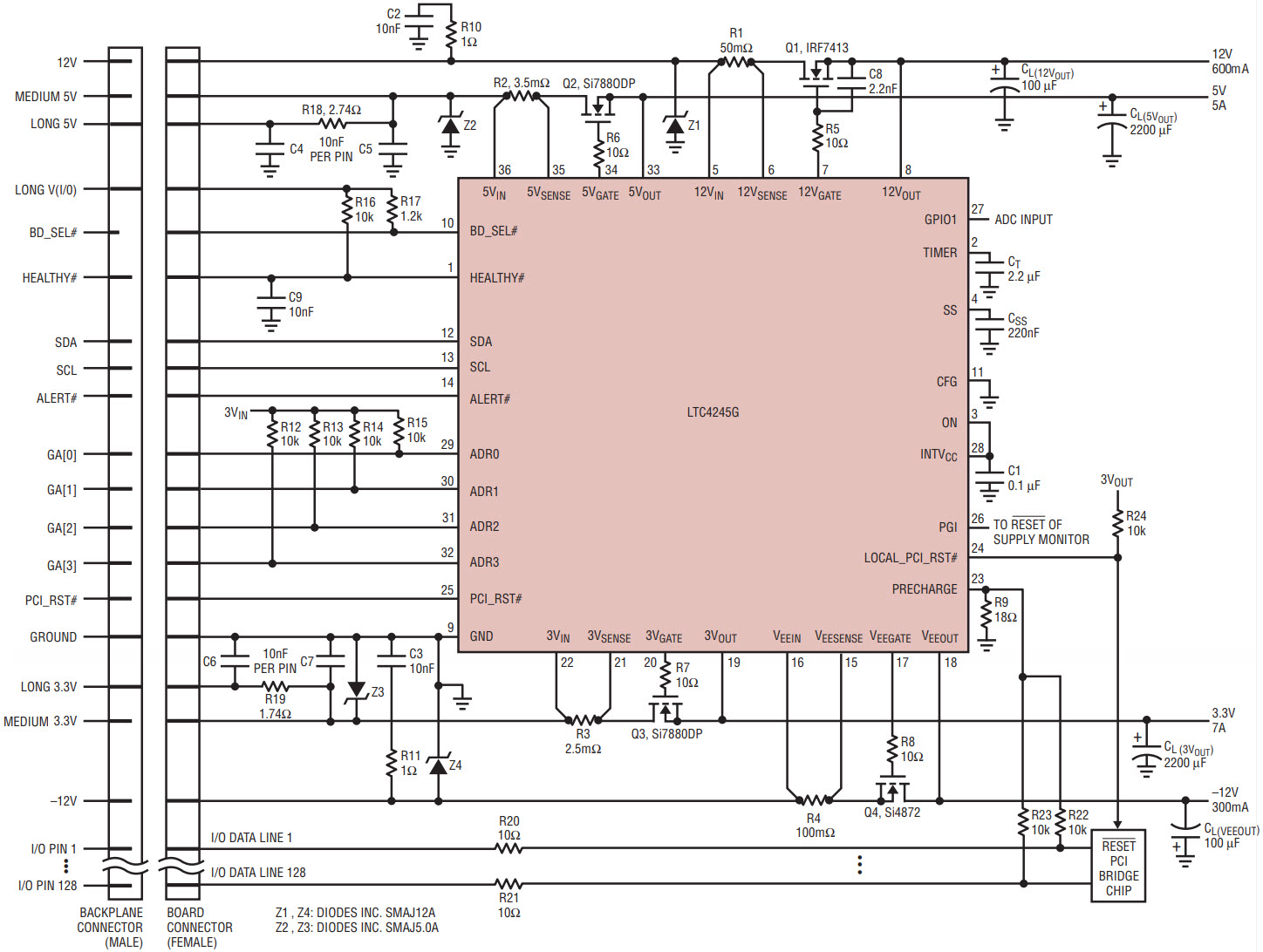
Figure 1. CompactPCI Hot Swap board application using the LTC4245 to control and monitor power on ±12V, 5V and 3.3V supplies. The bus I/O lines are precharged to 1V during insertion and extraction. The CPCI geographical slot address is used to set the I2C slave address of the part.
The CPCI male connector on the backplane has staggered pin lengths to ensure that all power supplies are physically connected before backend power is allowed to ramp. The following is a typical hot-plug sequence:
- ESD clips make contact.
- Long power (5V, 3.3V, V(I/O)) and ground pins make contact and the 1V PRECHARGE voltage becomes valid. Power is applied to the pull-up resistors connected to the HEALTHY# and BD_SEL# signals. LOCAL_PCI_RST# is held in reset. All power switches are held off.
- Medium length pins make contact. The internal low voltage supply (INTVCC) powers up from the 12V supply. Other connector pins that mate are HEALTHY#, PCI_RST# and the bus I/O pins (which are precharged to 1V).
- Short pin BD_SEL# makes contact. If it remains low for 100ms, the plug-in board power-up cycle may begin immediately. If the ON pin is tied high, turn-on is automatic, otherwise the LTC4245 waits for a serial bus turn-on command.
Power-Up Sequence
Figure 2 shows the backend supplies powering up after BD_SEL# goes low. Internal current sources charge up the gates to turn on the external switches. The TIMER pin is pulled up to 2.56V with 100µA and is then reset to ground by an internal switch. Current limit faults are ignored until TIMER falls to 0.23V. HEALTHY# pulls low at the end of this start-up timing cycle if all supply outputs are above their power bad thresholds. LOCAL_PCI_RST#, which was low, now follows PCI_RST#. A 10µA current pulls up on TIMER to start the power good input timeout cycle. The PGI pin must remain high at the end of the cycle, or all the switches are turned off.
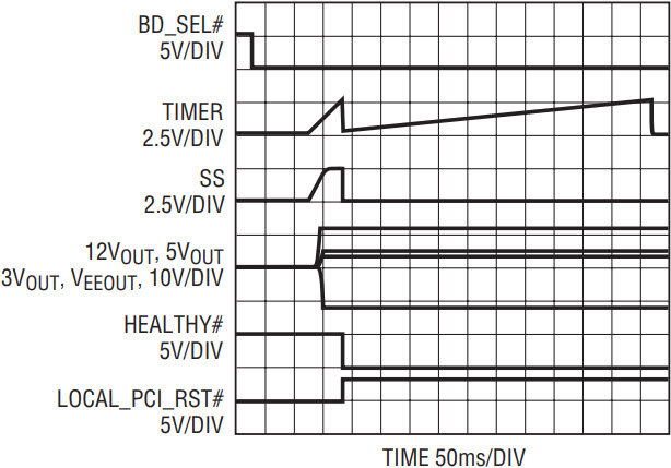
Figure 2. Typical power-up sequence activated 100ms after BD_SEL# goes low.
dI/dt Controlled Soft Start
The LTC4245 uses the capacitor at the SS pin to set the ramp rate of the inrush current (dI/dt) for each supply. Initially SS is at ground. At start-up it is pulled up with a 20µA internal current source. Each supply has a current limit amplifier that servos the gate of its external MOSFET so that the inrush current never exceeds an internal current limit set by the SS pin voltage. The voltage ramp on the SS pin sets the rate of rise of this internal limit. When the gate voltage reaches the MOSFET threshold voltage, the switch begins to turn on. The amplifier modulates the gate pull-up current so that the sense resistor voltage drop follows the internally set current limit. Figure 3 shows this for the 3.3V supply.
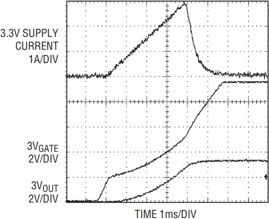
Figure 3. dI/dt controlled soft-start on 3.3V supply during sequenced turn-on. Inrush current rise rate of 750mA/ms is set by the SS pin capacitor.
Isolating Faults Prevents System Resets
The other job of a Hot Swap controller, apart from controlling inrush current, is to prevent faults on the output from propagating to the input and affecting other boards in the system. The LTC4245 features an electronic circuit breaker with a 20µs filter and a fast current limit at 3× the circuit breaker threshold for each supply. In the event of a short circuit at the output, the fast current limit pulls the gate of the MOSFET to the source in less than 1µs. Figure 4 illustrates this for the 12V supply. This limits the fault current and prevents damage to board traces and connector pins. The 20µs filter prevents temporary load current surges from activating the gate pull-down, eliminating unnecessary board resets.
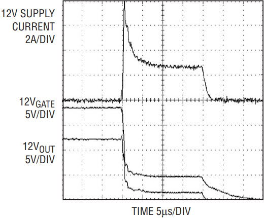
Figure 4. Fast current limit responds to a short-circuit on 12V output in less than 1µs, by pulling down 12VGATE to 12VOUT. 20µs later, the internal circuit breaker timer expires and all switches are turned off.
During start-up, if any of the supply outputs has a short to ground, the ramping internal current limit is folded back to a lower value to minimize MOSFET power dissipation. If a supply is still in current limit at the end of the start-up timing cycle, all switches are turned off and the TIMER pin goes through a cool-down timing cycle using a 2µA pull-up current. If overcurrent auto-retry is enabled, the 2% duty-cycle protects the MOSFET from excessive heating.
Switch On Supplies in Any Order
The ON and BD_SEL# pins can be used to turn the external MOSFET switches on or off. The BD_SEL# pin must be low for 100ms and ON pin set high to turn all switches on. The 100ms delay takes care of pin debounce when the BD_SEL# signal goes across a connector to implement detection of card insertion and extraction. The default LTC4245 behavior is to turn-on all switches together under the control of a single TIMER and SS cycle, as shown in Figure 2.
The turn-on behavior can be modified by writing to the ON and CONTROL registers through the I2C interface. Setting the sequence bit in the CONTROL register before taking BD_SEL# low turns the switches on in a 12V, 5V, 3.3V, –12V sequence. This is shown in Figure 5. The most flexible turn-on behavior is afforded by the ON register. For this the ON pin should be set low. Now when BD_SEL# goes low the switches remain off. The ON register has four bits to control the state of each supply switch. Writing a one to any of these bits turns on that particular switch. In this way a host controller can turn on the supplies in any desired sequence or combination.
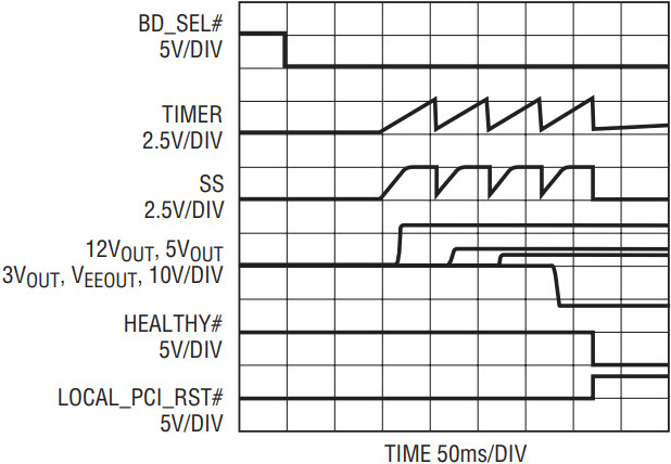
Figure 5. By setting the Sequencing Enable bit in the CONTROL register before taking BD_SEL# low, the supplies turn on in a 12V, 5V, 3.3V, –12V sequence. Compare this to Figure 2.
Extensive Fault Information Aids Diagnosis
If a board fault occurs, diagnosing the problem is simplified by checking the LTC4245’s onboard fault information. One status and two fault registers contain a record of faults that are present or have occurred.
The STATUS register reports if any supply is in an undervoltage or power bad state and if any switch is potentially shorted. It also indicates the state of the SS, PCI_RST#, LOCAL_PCI_RST#, BD_SEL# pins and the ADC. The fault registers log any faults that have occurred but may no longer be present. Individual bits record input undervoltage, output power bad and overcurrent faults on each supply. Each of these faults has an auto-retry bit in the CONTROL register. If a fault occurs and its auto-retry bit is set, then once the fault is removed the LTC4245 turns on the external switches automatically. Otherwise the switches are latched off until the fault bit is cleared.
Another 8-bit register called the ALERT register controls whether the occurrence of a particular kind of fault triggers the LTC4245 to pull the ALERT# pin low. This can be used to interrupt a host controller in real-time so it can query the LTC4245 register information and take appropriate remedial action. When multiple LTC4245s are present in a system, the SMBus Alert Response Protocol can be used to find the faulting LTC4245. The default behavior is to not pull ALERT# low for any fault.
Flexible Supply Configuration
The CFG pin on the LTC4245 can be used to deal with applications that do not utilize a –12V supply, or use another 3.3V supply instead of 5V. In a normal CPCI application the CFG pin is tied low. When the –12V supply is absent, the CFG pin is left unconnected. In this case, the LTC4245 disables the undervoltage lockout and power bad comparators on –12V, thus allowing 12V, 5V and 3.3V to power-up. By tying the CFG pin to INTVCC, not only is the –12V undervoltage and power bad ignored but 5V thresholds change to 3.3V levels.
Figure 6 shows the LTC4245 on a PCI Express backplane controlling one 12V and two 3.3V supplies. The VEE pins are all tied to ground. PRST#1 and PRST#2 signals sense when the plug-in card is seated. These signals are used by the PCI Express Hot-Plug Controller to command the LTC4245 to turn the switches on and off. Figures 7 and 8 show the LTC4245 controlling just two supplies, one of them 12V, the other being either 3.3V or 5V.
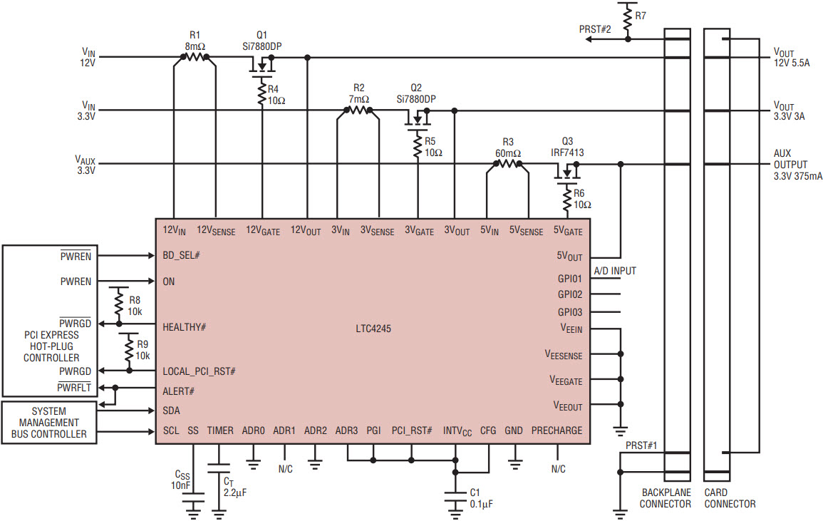
Figure 6. PCI Express backplane application to hot-plug and monitor 12V, 3.3V main and 3.3V auxiliary power. Tying the CFG pin to INTVCC lowers the 5V undervoltage and power bad thresholds to 3.3V levels, while also disabling those functions on the VEE pins.
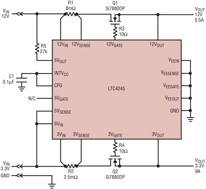
Figure 7. A 12V and 3.3V application, similar to Figure 6, but one less 3.3V supply.
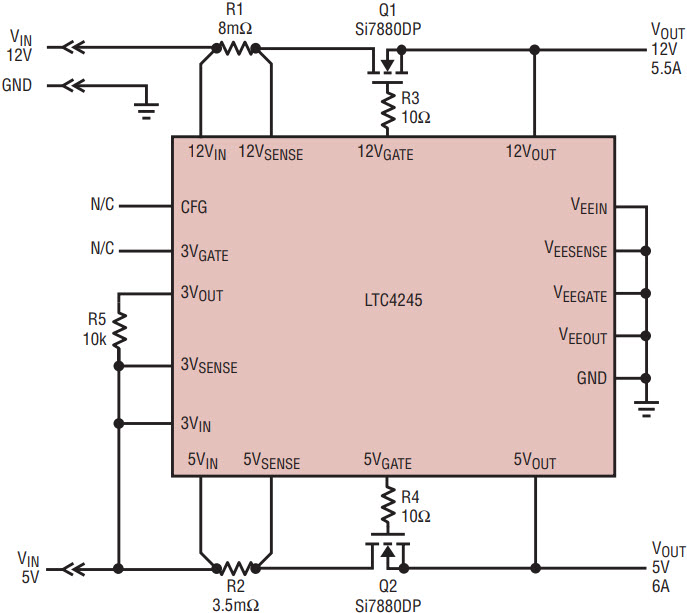
Figure 8. A 12V and 5V application. Floating the CFG pin disables the VEE undervoltage and power bad functions, allowing those pins to be tied to GND.
Conclusion
The LTC4245 packs a 4-supply Hot Swap controller, ADC, I2C interface and numerous other features into a 5mm × 7mm QFN package, simplifying the task of inrush control, fault isolation and power monitoring on a plug-in board. The simple default behavior can be customized through onboard registers. It provides a space-saving Hot Swap solution for any high-availability system utilizing multiple supplies such as CompactPCI or PCI Express.


