Combining Distributed Read with Chain Mode Using the LTC2380-24
Distributed read allows the data of the LTC2380-24 collected over N samples to be read out over each of those samples one bit or a few bits at a time, reducing the frequency of SCK allowing even the relatively slow μcontrollers to keep up. Chain mode allows multiple LTC2380-24s to be daisy-chained together so that only three lines CONV, SCK and SDO are required no matter how many ADCs are communicating with the μcontroller. This is useful for applications where hardware constraints such as only one SPI port, limit the number of control lines available. This also allows the ADCs to convert simultaneously for applications where phase information is important. Both of these functions can be used simultaneously as shown in the following application.
The circuit of Figure 1 shows two LTC2380-24 ADCs chained together communicating with a single μcontroller over three lines. Any number of ADCs could be chained together using only the same three lines but for the sake of simplicity this example will only deal with two.

Figure 1. Two LTC2380-24s Operating in Chain Mode.
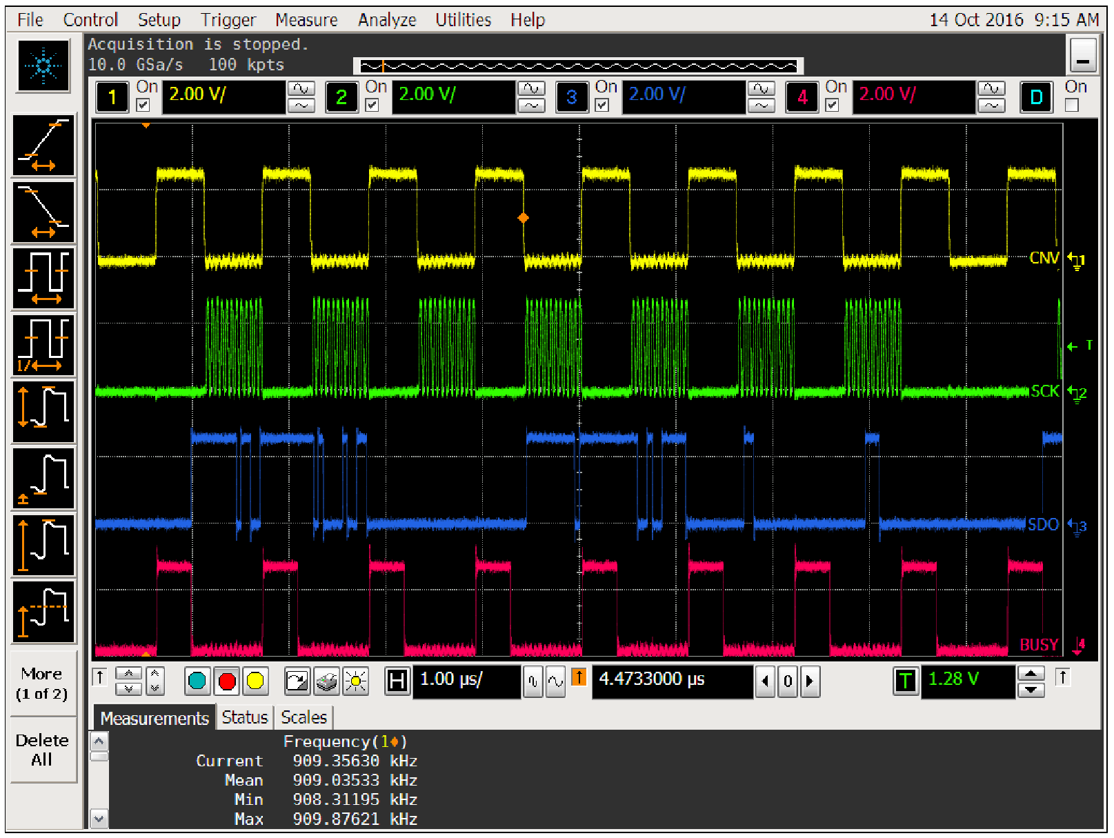
To transfer the 40-bits of data from each ADC will require a minimum of 80 SCK pulses. The distributed read rules for the LTC2380-24 require that there be at least 1 but less than 20 SCK pulses during each conversion cycle to keep the internal I/O register from resetting. To prevent having to deal with a scaling factor, N will be a power of 2. Again for the sake of simplicity the smallest N possible, 8, will be chosen. This means that for 7 cycles 12-bits will be clocked out and for the 8th cycle no bits will be clocked, resetting the I/O register and starting a new average. This will clock out a total of 84-bits. 80 of these will be the data and number of averages information from the two ADCs and the remaining four bits will always be zeros. An oscilloscope photo of the eight conversion cycles and data transfer is shown in Figure 2. The image of Figure 2 uses a 40MHz SCK frequency to transfer the results of two ADCs converting at approximately 0.989Msps. The output data rate is 123ksps/ADC. This may still be too fast for some μcontrollers. To reduce the SCK frequency, a lower output data rate can be obtained by reducing the conversion frequency or increasing the value of N. Note that no data is clocked until the conversion is finished (BUSY goes low) to prevent transitions on the SCK line from corrupting the conversion result. Figure 3 shows that the SCK line does not transition within 10ns of the rising edge of CNV which is required by the tquiet specification. The first 40-bits of the transfer are shown in Figure 4. During the first two conversion cycles of this time the 24 data bits are transferred on the rising edge of each SCK pulse followed by the number of samples averaged during the next 16 SCK pulses. The 16-bit number of samples averaged word contains the number of samples averaged - 1. For this example (N = 8) that means the three LSBs should all be 1s corresponding to the number 7 in binary. This can be seen in Figure 5 which zooms in even further to show the rising edges of clocks 37 - 40. The second 40-bits are clocked out in a similar manner followed by the last four bits which are always zeros.

Figure 2. LTC2380-24 Distributed Read with Chain Mode.

Figure 3. SCK Does Not Transition Within 10ns of the Rising Edge of CNV.

Figure 4. Zoomed Image of Data Transfer Showing the First 40 Clocks.

Figure 5. Rising Edges of Clocks 37-40 of the Data Transfer.
The example presented here demonstrated how to use the LTC2380-24 combining both distributed read and chain mode to efficiently transfer the results of two ADCs over only three wires using a modest clock frequency. This technique can be expanded to include any number of ADCs without increasing the number of data lines required.
著者について
Bob Dobkin氏、Bob Widlar氏、Carl Nelson氏、Tom Redfern氏の指導の下、オペアンプ、コンパレータ、スイッチング・レギュレータ、A/Dコンバータ(ADC)など、様々な製品を担当。この時期には、...


