1.2MHz ThinSOT Boost Converter Operates from a Single Cell, Saves Board Space and Delivers 93% Efficiency
1.2MHz ThinSOT Boost Converter Operates from a Single Cell, Saves Board Space and Delivers 93% Efficiency
著者
John Bazinet
2001年09月01日
Introduction
Many portable handheld electronic devices require small, high efficiency power converter solutions to extend the time between recharge cycles or battery replacement. Linear Technology’s new LTC3400 family of products address this need by integrating a fixed frequency, internally compensated, synchronous boost converter in a 3mm × 3mm × 1mm ThinSOT package. The 1.2MHz switching frequency and built-in features minimize the solution footprint and enable the use of tiny, low profile inductors and ceramic capacitors.
With the ThinSOT package and a few external components, a complete, 90% efficient, single-cell to 3.3V/150mA converter occupies only 7mm × 9mm of precious board real estate. Efficiencies as high as 93% can be obtained from two cells with the solution occupying minimal board space. An external, low current Schottky diode, although not required, will maximize efficiency.
The LTC3400 operates from an input voltage below 1V and can provide output voltages in the range of 2.5 to 5V. Once started, the LTC3400 will continue to operate with an input voltage as low as 0.5V, with the only limitation being the ability of the input power source to supply sufficient power. This feature eliminates the need for a large input bypass capacitor, saving board space and cost. Referring to Figure 1, the LTC3400 achieves its high efficiency with low gate charge internal switches rated at 0.35Ω (N) and 0.45Ω (P) typical. Switch current limit is guaranteed to be greater than 600mA over the full operating temperature range, enabling output power of 0.5W with a single AA cell input and 1W from two cells. Current mode control delivers excellent input line and output load transient response. Slope compensation is built-in along with circuitry to maintain a constant current limit threshold regardless of input voltage. Internal feedback loop compensation eliminates the need for external components, lowering overall cost and simplifying the design process.
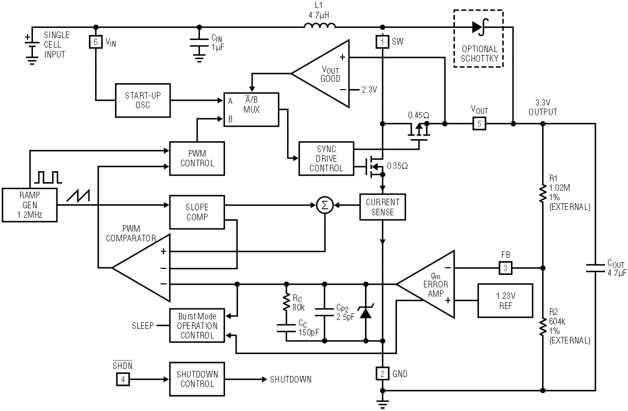
Figure 1. LTC3400 block diagram.
Burst Mode™ operation improves converter efficiency at light loads by cycling the power converter on only when required to keep the output voltage within a regulation band. Once the output voltage is in regulation, the converter switches to a sleep state, significantly reducing both gate charge losses and quiescent current. The LTC3400 includes Burst Mode functionality, whereas the LTC3400B does not, electing to maintain fixed frequency operation at lighter loads. Using Burst Mode operation, the LTC3400 consumes only 19µA of quiescent current. Aside from this small difference, the LTC3400 and LTC3400B are identical. The Shutdown input can be driven with standard CMOS logic above either VIN or VOUT (up to 6V maximum) and has 250mV of hysteresis. Quiescent supply current in shutdown is <1µA. Shutdown hysteresis allows for a simple resistive pull-up to VIN for continuous operation.
Single-Cell to 3.3V, 500mW Converter in 7 × 9mm
The circuit of Figure 2 converts a single-cell input to 3.3V while occupying a minimal amount of board real estate. Tiny ceramic input and output capacitors are employed for this design. Maximum output current is 150mA. Efficiency vs load current is displayed in Figure 3. A 40mA to 100mA load step response is shown in the oscilloscope photograph in Figure 4. The transition from Burst Mode operation to fixed frequency operation is shown in Figure 5. Note that the peak-to-peak ripple voltage using Burst Mode operation is still less than 1%. This circuit will also work well with a 2-cell input, delivering up to 1W of output power. The 2-cell input improves efficiency by a few points (Figure 3), due primarily to the lower input current required.
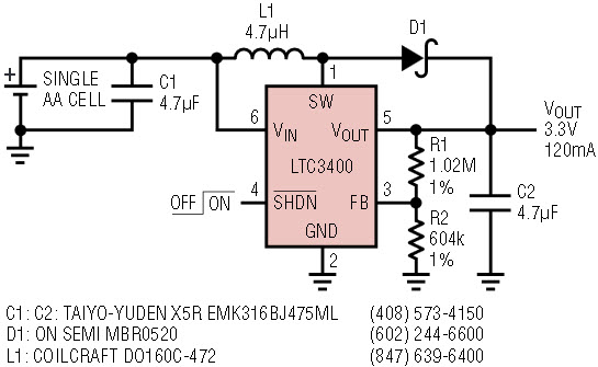
Figure 2. Single cell to 3.3V synchronous boost converter.

Figure 3. Efficiency vs load current for Figure 2’s circuit.

Figure 4. 40mA to 100mA load step response for Figure 2’s circuit.
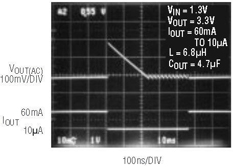
Figure 5. Fixed frequency and Burst Mode operation for Figure 2’s circuit.
Lithium-Ion to 5V, 1.6W High Efficiency Converter
A 5V supply is still required in certain types of portable equipment, often at lower power levels. It is advantageous to develop this voltage with minimal cost and board space, but not at the expense of good efficiency. The circuit of Figure 6 is a complete 5V, 300mA power converter with a peak efficiency of 93% (Figure 7). Operating from a single Lithium-Ion battery, the circuit of Figure 6 delivers 90% or greater efficiency over a load range from approximately 30mA to 240mA. As in the previous circuit, ceramic input and output capacitors are employed. The total board area is only 8mm × 9mm. A small, inexpensive Schottky rectifier is recommended for this circuit as it improves efficiency by approximately 2% to 3%. This circuit will work equally well with a fixed 3.3V input for spot regulation applications where an inexpensive, efficient 5V supply is needed.
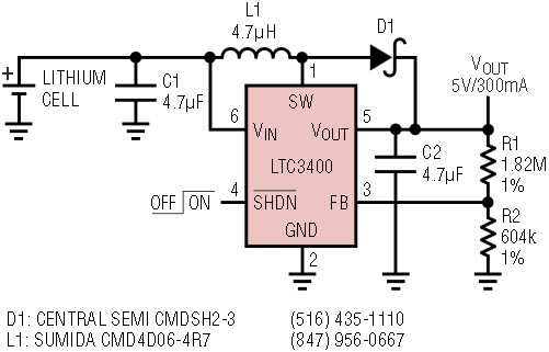
Figure 6. Single lithium cell to 5V, 300mA converter.
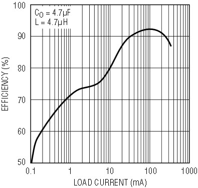
Figure 7. Efficiency vs load current for Figure 6’s circuit.
Component Selection
The LTC3400 requires only a few external components to build a wide variety of low voltage, low power converters. The proper selection of these components will ensure the best possible performance. The most important component is the inductor. Several manufacturers offer suitable inductors for use with the LTC3400 (see Table 1). These have been selected for their performance characteristics, small size, and low cost. X5R ceramic VIN and VOUT bypass capacitors are recommended for use with the LTC3400. A simple voltage divider programs VOUT:

Finally, an optional Schottky diode may be added across the synchronous rectifier in order to maximize efficiency.
| Part | L (μH) | Max DCR (mΩ) | Height (mm) | Vendor |
| CDRH5D18-4R1 | 4.1 | 57 | 2.0 | Sumida (847) 956-0666 www.sumida.com |
| CDRH5D18-100 | 10 | 124 | 2.0 | |
| DRH3D16-4R7 | 4.7 | 105 | 1.8 | |
| CDRH3D16-6R8 | 6.8 | 170 | 1.8 | |
| CR43-4R7 | 4.7 | 109 | 3.5 | |
| CR43-100 | 10 | 182 | 3.5 | |
| CMD4D06-4R7MC | 4.7 | 216 | 0.8 | |
| CMD4D06-3R3MC | 3.3 | 174 | 0.8 | |
| DS1608-472 | 4.7 | 60 | 2.9 | Coilcraft (847) 639-6400 www.coilcraft.com |
| DS1608-103 | 10 | 75 | 2.9 | |
| DO1608C-472 | 4.7 | 90 | 2.9 | |
| D52LC-4R7M | 4.7 | 84 | 2.0 | Murata (formerly Toko) www.murata.com |
| 52LC-100M | 10 | 137 | 2.0 | |
| LQH3C4R7M24 | 4.7 | 195 | 2.2 | Murata (814) 237-1431 www.murata.com |
Conclusion
The LTC3400 and LTC3400B in the ThinSOT package produce very compact, high efficiency power converters. Single-cell operation is guaranteed. External components count is minimized without sacrificing performance.
著者について
John Bazinet has over 30 years experience as an architect, group director, strategist and developer of innovative, high performance power management solutions. He established and directed Linear Technology's New Hampshire ...


