概要
設計リソース
評価用ボード
型番に"Z"が付いているものは、RoHS対応製品です。 本回路の評価には以下の評価用ボードが必要です。
- EVAL-ADICUP3029 ($52.97) Ultra Low Power Arduino form factor compatible Development Platform
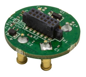
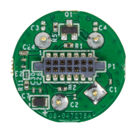
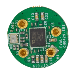
- EVAL-CN0429-EBZ ($58.85) Electrochemical Gas Sensor Board
- EVAL-M355-ARDZ-INT ($58.85) ADuCM355 based Sensor Interposer Board
機能と利点
- 3-, 4-wire Sensor Compatible
- Supports Multiple Gas Sensor
- Onboard Temperature and Humidity Sensor
- Gas Sensor Diagnostics and Life Expectancy
製品カテゴリ
マーケット & テクノロジー
使用されている製品
参考資料
回路機能とその特長
Gas detection instruments are used in a wide range of applications ranging from home air quality measurement devices to industrial solutions for detecting toxic gases. Many of these instruments use electrochemical gas sensors. This sensor technology requires specialized front-end circuitry for biasing and measurement.
By utilizing built-in diagnostics features (such as impedance spectroscopy or bias voltage pulsing and ramping) it is possible to inspect sensor health, compensate for accuracy drift due to aging or temperature, and estimate the remaining lifetime of the sensor right at the edge of the sensor network without user intervention. This functionality allows smart, accurate sensor replacement at the individual edge nodes. An integrated, ultra low power microcontroller directly biases the electrochemical gas sensor and runs onboard diagnostic algorithms.
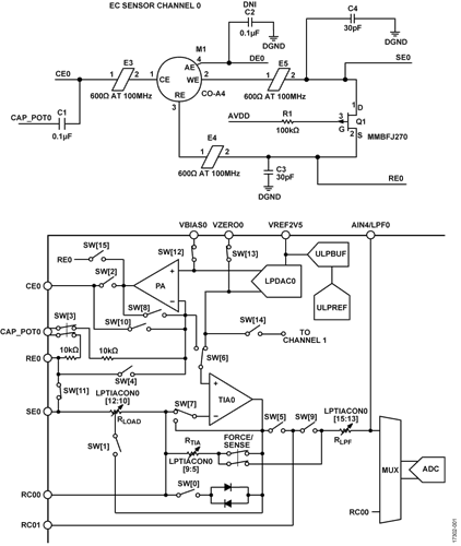
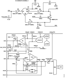
The circuit shown in Figure 1 shows how an electrochemical gas sensor is connected to the potentiostat circuit and how it is biased and measured. Common 2-lead, 3-lead, and 4-lead electrochemical gas sensors can be used interchangeably. The integration of this signal chain dramatically reduces cost, size, complexity, and power consumption at the sensor node.

回路説明
Fundamentals of Electrochemical Gas Sensors
The fundamental principle of electrochemical gas sensing is measuring the current generated due to oxidation or reduction at an electrode in response to a target gas. Most common sensors have two or three electrodes. Some sensors utilize an additional fourth electrode. In 3-electrode configuration, the electrodes are referred to as a working electrode (WE), also known as sensing electrode (SE), a reference electrode (RE), and a counter electrode (CE). Figure 2 shows simplified diagram of such an electrochemical cell.

The target gas enters the sensor chamber through the porous working electrode and diffuses into the electrolyte (most commonly acid), where it is either oxidized or reduced. Electric current generated by this reaction is then sensed and converted to a corresponding voltage level by the external potentiostat circuit. A continuous or pulsed bias voltage is often required to be applied across sensor electrodes to ensure optimal performance. In the case of a 3-electrode sensor, the bias voltage is applied between the RE and WE. An equal but opposite reaction to the one occurring between the RE and WE occurs at the CE. If reduction occurs at the WE, oxidation occurs at the CE. Further information about operation of the potentiostat circuit is available in the ADuCM355 Hardware Reference Manual.
Electrochemical Gas Sensor Connections to ADuCM355
The data sheet for the gas sensor specifies a bias voltage required for normal electrochemical behavior of the sensor. The bias voltage is the voltage difference between the RE and the SE/WE. This differential voltage is set by the outputs of a low power, digital-to-analog converter (LPDACx). The LPDACx has two outputs, an output with 12-bit resolution (VBIASx) and an output with 6-bit resolution (VZEROx). The VBIASx output of the LPDACx is internally connected to the noninverting terminal of the power amplifier (PA). Externally, VBIASx must be connected to the AGND pin via a 100 nF capacitor. The output of the PA amplifier connects directly to the sensor’s CE. The feedback to the inverting terminal of the PA amplifier is from the RE pin of the sensor; therefore, the VBIASx voltage determines the RE pin voltage.
The VZEROx output of the LPDACx is internally connected to the noninverting terminal of the low power, transimpedance amplifier, LPTIAx. Do not use this pin as a voltage source for an external circuit. It is recommended to connect this pin to the AGND pin.
The electrochemical gas sensor itself is only connected to the ADuCM355 via the REx, CEx, and SEx terminals, respectively, allowing the optional fourth terminal to be used for the diagnostics electrode (DEx), as shown in Figure 1.
The effective sensor bias voltage is obtained using following equation:

The VZERO voltage is recommended to be set to 1100 mV, and the VBIAS voltage is then to be set with respect to the sensor bias voltage value from the sensor data sheet.
Depending on the sensor type, bias voltage may also be negative. The following equations explain how to configure the DAC for both positive and negative bias voltages.
When the required bias voltage is positive, (12-bit output ≥ 6-bit output),

When the required bias voltage is negative (12-bit output < 6-bit output),

where:
LPDACDAT is the low-power DAC data-out control register.
0.54 mV is approximately 1 LSB of the 12-bit DAC.
34.38 mV is approximately 1 LSB of the 6-bit DAC.
The sensing/working electrode (WE) of the sensor is connected to the LPTIAx via the inverting input pin SEx. The LPTIAx has a programmable load resistor (RLOAD) and programmable gain resistor (RTIA). The current flowing in/out of the sensors SE electrode reflects the target gas in the atmosphere around the sensor. The sensor datasheet reflects this in current/ppm. The LPTIAx amplifier converts the current to a voltage that is then buffered and measured via the analog-to-digital converter (ADC). Select the RTIA resistor value so that it maximizes the ADC input range of ±900 mV. The RTIA value is calculated using following equation:

where:
0.9 V is the ADC input range.
Sensitivity is defined as nA/ppm.
Max_Range is the maximum range of the sensor in ppm.
The microcontroller can calculate the current flowing in/out of the SEx pin and determine the ppm level of the target gas.
For more detailed information about the equations used, see the ADuCM355 Hardware Reference Manual.
Sensor Health Diagnostics and Life Expectancy
The lifespan of an electrochemical gas sensor varies between manufacturers as well as between different target gases. Information about expected lifetime can be found in sensor manufacturer data sheets. The actual lifespan, however, varies strongly depending on storage and operating conditions.
The lifetime of an electrochemical gas sensor and the regular need for calibration are the most challenging aspects of this type of sensor. Therefore, it is desirable to have the ability to monitor sensor’s health directly in the instrument.
The built-in waveform generator and discrete Fourier transform (DFT) block of the ADuCM355 enable impedance spectroscopy measurement by applying an ac signal sweep to the counter electrode. This measurement indicates the quality of charge transfer between electrodes, effectively detecting aging of the sensor’s electrolyte. Laboratory tests show good correlation between impedance and sensitivity of the sensor.
Other methods of detecting sensor health include pulse test and ramp test. For these tests, a voltage pulse or ramp is applied on top of the bias voltage to test the sensor responsivity and charge transfer, respectively.
All of these measurements in conjunction with algorithms running on the ADuCM355 contribute to improving the accuracy, performance, and lifetime of the electrochemical gas sensor. Enabling this level of smart diagnostics and prognostics requires that a large set of sensors be characterized by tests such as accelerated aging. Contact the sensor manufacturer for this type of data.
Temperature and Humidity Compensation
An external temperature and humidity sensor is provided on the sensor board. It is connected to the ADuCM355 via an I2C interface. The performances of most electrochemical sensors varies with both temperature and humidity, and therefore compensation for these influences is required.
バリエーション回路
The circuit was tested with 3-lead electrochemical gas sensors (CE, RE, WE). However, it can also support 4-lead (CE, RE, WE1, WE2) and 2-lead sensors (CE and WE).
Four-lead sensors use several electrode configurations. The fourth electrode can be used as an additional diagnostics electrode (DE).
Some sensors can detect two gases, in which case the fourth electrode is configured as a working electrode (for example, a combined CO and H2S sensor).
回路の評価とテスト
This circuit uses the EVAL-CN0429-EBZ gas sensor board, the EVAL-M355-ARDZ-INT shield board, and the EVAL-ADICUP3029 Arduino-compatible platform board. A user guide for this platform is available at www.analog.com/EVAL-ADICUP3029.
Equipment required
The following equipment is needed:
- PC with a USB port and Windows® 7 (32-bit) or higher
- EVAL-ADICUP3029 Arduino-compatible platform loaded with CN-0429 firmware
- EVAL-M355-ARDZ-INT shield board
- EVAL-CN0429-EBZ gas sensor board
- Suitable electrochemical gas sensor (such as the Citytech 4CF+ CiTiceL CO sensor or Alphasense CO-A4 sensor),
- USB type A to USB micro cable
- Serial terminal software (PuTTY, TeraTerm or similar)
- Carbon monoxide alarm tester spray (optional, for CO sensors only) or other source of target gas
System Setup
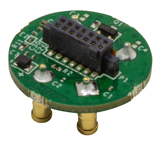
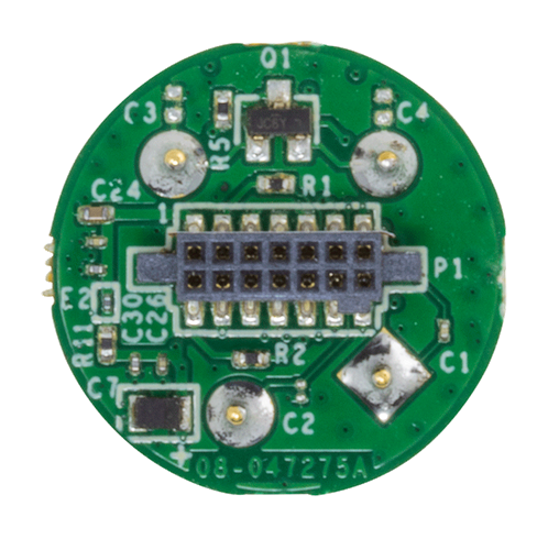
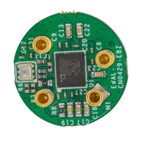
The measurement system consists of a motherboard (EVAL-ADICUP3029), an interposer board, and up to four gas sensors daughter boards (see Figure 3). This four gases configuration is widely used in both toxic gas and air quality applications.
Sensor data acquired by the system is sent to a PC via a virtual COM port interface, where they can be displayed and processed.
To set up the circuit for evaluation, take the following steps:
- Plug the four EVAL-CN0429-EBZ boards into the EVAL-M355-ARDZ-INT shield board, followed by the EVAL-ADICUP3029 circuit board.
- Ensure that the switch settings are correct on both the EVAL-M355-ARDZ-INT and EVAL-CN0429-EBZ evaluation boards.
- Connect the EVAL-ADICUP3029 virtual COM USB port to the PC.
- Set up the serial terminal software to match the setting of the CN-0429 firmware and select the correct virtual COM port.
- Press the reset button on the EVAL-ADICUP3029 board, and the software displays the steps of gas measurements.
The EVAL-CN0429-EBZ boards ship with dedicated firmware, but provisions are available to program new firmware. The EVAL-CN0429-EBZ boards can be programmed over USB by the debugger section of the EVAL-ADICUP3029. However, this requires cutting three traces and using the included cable to connect to EVAL-M355-ARDZ-INT. Other options are to use an additional EVAL-ADICUP3029, or to use an external debugger. See the CN-0429 User Guide for detailed instructions.

Communications Interface
The example code for the EVAL-ADICUP3029 provides a simple user interface by means of a virtual COM port between the EVAL-ADICUP3029 microcontroller and the PC. The user interface can be accessed using a serial port terminal application like TeraTerm. This interface enables the user to configure the sensor and read the sensor data. Further information about the operation of this user interface can be found in the CN-0429 User Guide.

The 14-pin connector on the sensor board provides power, as well as SPI, I2C, and UART communication interfaces. Any of these interfaces can be used to communicate with the sensor board if the user decides not to use the EVAL-M355-ARDZ-INT. Which interface is used depends on user preferences and the firmware loaded on the ADuCM355. If achieving the lowest possible supply current is critical, it is recommended to use the SPI interface.
Test
The system performance was evaluated by measuring the concentration of CO gas in a calibrated gas chamber. A comparison of the measurements of two different CO sensors is shown in Figure 5.
Other, simpler test methods can be used to quickly verify basic circuit functionality. Many sensors show some response when breathed on. Alternatively, a nontoxic carbon monoxide alarm tester spray can be used to excite the sensor.

