Design Note 364: High Accuracy Synchronous Step-Down Controller Provides Output Tracking and Programmable Margining
Introduction
Output voltage tracking and margining are two increasingly popular features in power supply designs for high performance server, ASIC and memory systems. These two functions are among the advanced features provided in the LTC3770, a wide operating range, high accuracy, synchronous step-down DC/DC controller. The LTC3770 operates with input voltages from 4V to 32V, generating output voltages down to 0.6V with its highly accurate ±0.67% 0.6V reference voltage. It has a constant on-time, valley current mode control architecture, which allows the LTC3770 to operate at very low duty cycles with fast transient response. The current sensing resistor is optional: leave it out for high efficiency, or in for most accurate current limit.
Figure 1 shows a 2.5V, 10A power supply with a 5V to 28V input range. The switching frequency of the converter can be selected by an external resistor, RON, and is compensated for variations in input supply voltage, or the controller can be synchronized to an external clock via an internal phase-lock loop. Figure 2 shows the efficiency of the circuit versus load current.
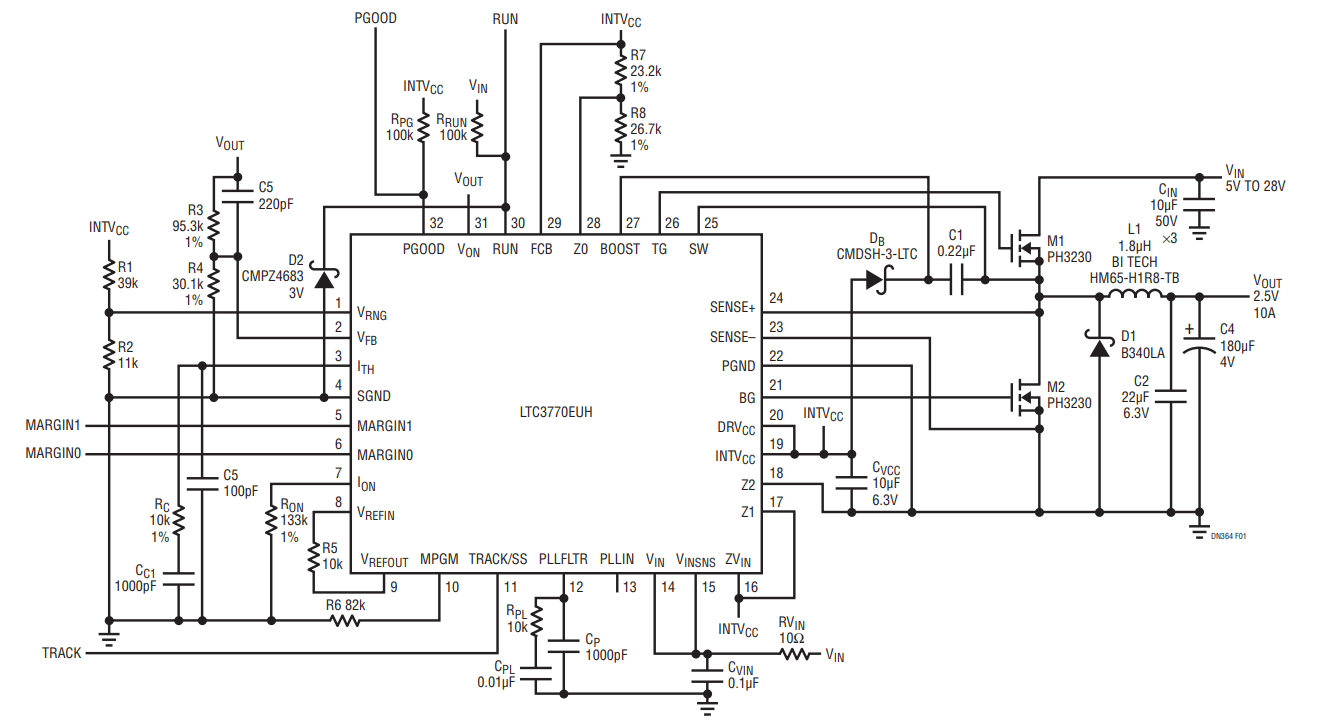
Figure 1. High Efficiency 5V-28VIN to 2.5V/10A Synchronous Buck Converter with Tracking and Margining.
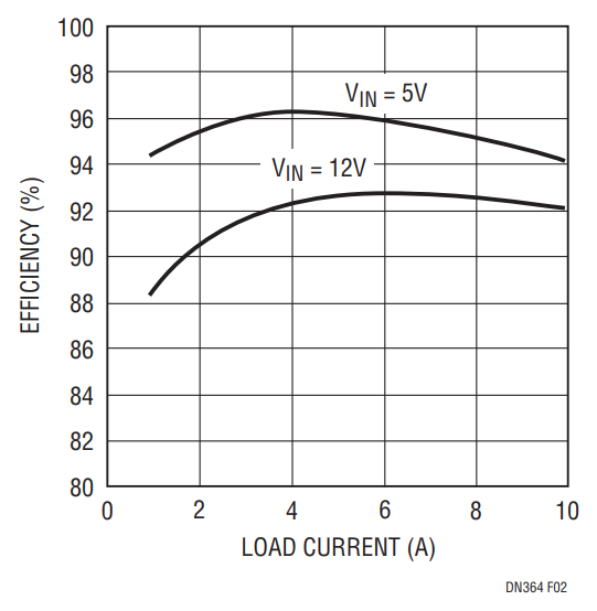
Figure 2. Efficiency Curves of the LTC3770 Converter in Figure 1.
Start-Up and Shut Down Output Tracking
The LTC3770 output voltage can track another supply via the TRACK/SS pin. Tracking and sequencing functions allow the user to easily optimize the start-up and shut down of multiple supplies, such as system core and I/O supplies. The tracking can be coincident or ratiometric, as shown in Figure 3.
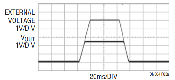
Figure 3b. Ratiometric Tracking.
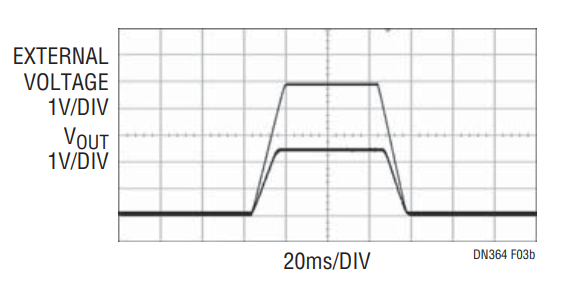
Figure 3b. Ratiometric Tracking.
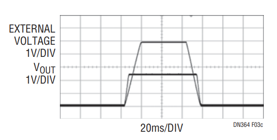
Figure 3c. Special Ratiometric Tracking.
Programmable Voltage Margining
Voltage margining is the dynamic adjustment of the output voltage to its worst-case operating value during production test in order to stress the load circuitry, verify control/protection functionality of the board and confirm system reliability. The LTC3770 has two logic control pins, MARGIN1 and MARGIN0, to enable margin up for higher output voltage or margin down for lower output voltage. Table 1 shows a summary of the configurations.
| MARGIN1 | MARGIN0 | MODE |
| Low | Low | No Margining |
| Low | High | Margin Up |
| High | Low | Margin Down |
| High | High | No Margining |
The magnitude of the margin voltage shift is programmed by selecting the ratio of two resistors, R5 and R6 in Figure 1. When the margining function is enabled, the error amplifier reference voltage is adjusted to:

For example, ±5% margining can be achieved by selecting R5 = 13k and R6 = 510k.
Additional Features
The LTC3770 provides very strong gate drivers allowing up to 25A output currents, programmable current limit, output overvoltage protection and input undervoltage lockout. Other features include power good monitor, programmable soft-start, selectable discontinuous operation mode or forced continuous mode at light load and adjustable dead time between the top gate and bottom gate signals to optimize efficiency.
Conclusion
The LTC3770 has an accurate 0.6V reference voltage and a wide operating range. It includes advanced functions usually implemented by additional ICs—such as output tracking and programmable voltage margining. Available package options are a thermally enhanced 5mm × 5mm QFN package and a leaded 28-pin SSOP.
著者
