Interfacing an SPI RTC with a Motorola DSP
要約
This application note provides an example of hardware and software for interfacing a Serial Peripheral Interface (SPI) RTC with a Motorola DSP that has a built-in SPI interface module. This example uses a Motorola DSP Demo kit as the basis for the circuit.
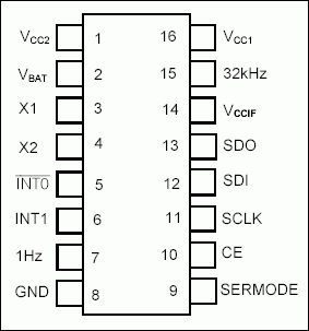
DS1306 Pin Configuration

Pin Configuration
Description
The DS1306 real-time clock (RTC) can be interfaced with a microcontroller (µC) or digital signal processing (DSP) unit using a 3-wire or an SPI™ interface. This application note shows how to connect a DS1306 to a Motorola DSP that has a built-in SPI interface module. The DS1305 could also be used in this application. This circuit uses the Motorola DSP56F800DEMO Demonstration Board and CodeWarrior IDE.
Using the Example Software
The example software was developed by starting with a blank project. Follow the instructions in the Motorola Kit Installation Guide (Tutorial: Creating a CodeWarrior Project) for details. Add the code included in this application note in main.c.
Operation
The program uses a GPIO port to control CE on the DS1306. The software initializes the SPI controller module in the DSP writes the time and date to the DS1306. The software then loops reading the time and date. The DS1305 and DS1306 support SPI modes 1 and 3.
Figure 1 shows a schematic of the circuit. This circuit comprises a daughter card that is attached to the Motorola demo board. Please note that the circuit in Figure 1 includes several RTCs with SPI interfaces. Only one RTC may be used at a time, and the software only supports the DS1306. The software is shown in Figure 2.
Figure 1. Daughter card for the DSP56F800DEMO board.
Figure 2. Code for demo.
/* File: main.c */
/* This example program was developed using the Motorola
56F800 Demo Board Kit. Follow the kit instalation guide
for creating a CodeWarrior Project. Use the shell of the
new project for this example. Note: This program is for
example only and is not supported by Dallas Semiconductor
Maxim. */

#include "port.h"
#include "stdio.h"
#include "stdlib.h"

/*******************************************************
* Main program for use with Embedded SDK
*******************************************************/

extern sampleASM (void);

void reset_spi(void);
void wbyte_spi(unsigned char);
unsigned char rbyte_spi(void);

#define      REG_BASE 0x0000
#define      SPI_BASE 0x0F20
#define      GPIOB_BASE 0x0FC0

#define      SPSCR *(volatile UWord16 *)(SPI_BASE + 0)
#define      SPDSR *(volatile UWord16 *)(SPI_BASE + 1)
#define      SPDRR *(volatile UWord16 *)(SPI_BASE + 2)
#define      SPDTR *(volatile UWord16 *)(SPI_BASE + 3)

#define      GPIO_B_PUR *(volatile UWord16 *)(GPIOB_BASE + 0)
#define      GPIO_B_DR *(volatile UWord16 *)(GPIOB_BASE + 1)
#define      GPIO_B_DDR *(volatile UWord16 *)(GPIOB_BASE + 2)
#define      GPIO_B_PER *(volatile UWord16 *)(GPIOB_BASE + 3)

void main (void)
{
unsigned char      min=0x58, sec=0x59, hr=0x09, dow=0x04, date=0x23,
                         mon=0x10, yr=0x03;

      reset_spi();

      GPIO_B_DR = 0;              // disble RTC - CS low

      GPIO_B_DR = 0x0008;         // enable RTC - CS high
      wbyte_spi(0x8f);            // control register write address
      rbyte_spi();                // dummy read
      wbyte_spi(0);               // disable write protect
      rbyte_spi();
      GPIO_B_DR = 0;              // disble RTC - CS low

      GPIO_B_DR = 0x0008;         // enable RTC - CS high
      wbyte_spi(0x80);            // select seconds register write address
      rbyte_spi();                // dummy read
      wbyte_spi(sec);             // seconds register data

      rbyte_spi();
      wbyte_spi(min);             // minutes register
      rbyte_spi();
      wbyte_spi(hr);              // hours register
      rbyte_spi();
      wbyte_spi(dow);             // day of week register
      rbyte_spi();
      wbyte_spi(date);            // date register
      rbyte_spi();
      wbyte_spi(mon);             // month register
      rbyte_spi();
      wbyte_spi(yr);              // year register
      rbyte_spi();
      GPIO_B_DR = 0;              // disble RTC - CS low

      while(1)
      {
             GPIO_B_DR = 0x0008;         // enable RTC - CS high
             wbyte_spi(0);               // seconds register read address
             rbyte_spi();                // dummy read
             wbyte_spi(0);
             sec = rbyte_spi();          // read seconds register
             wbyte_spi(0);
             min = rbyte_spi();          // ditto minutes
             wbyte_spi(0);
             hr = rbyte_spi();           // and so on
             wbyte_spi(0);
             dow = rbyte_spi();
             wbyte_spi(0);
             date = rbyte_spi();
             wbyte_spi(0);
             mon = rbyte_spi();
             wbyte_spi(0);
             yr = rbyte_spi();

             GPIO_B_DR = 0; // disable RTC - CS low
      }
      return;
}

//SPSCR
//15  14  13  12  11  10  9  8  7  6  5  4  3  2  1
0
// r MSB SPRF ERRIE  ovrf modf spte modfen spr1    spr0    sprie spmstr    cpol cpha
spe  spite

void reset_spi()
{
int   val;
      SPSCR = 0x0096;             // SPR0, SPMSTR, CPHA, SPE
      SPDSR = 0x0007;             // 8-bit size

      SPSCR &= 0xfffd;            // clear spe, resets SPI (partial)
      SPSCR |= 0x0002;            // set spe, new values take effect

      GPIO_B_PER = 0x00f3;        // use GPIOB3 as CS for RTC
      GPIO_B_DDR = 0x000c;        // direction is output
}

void wbyte_spi( unsigned char wbyte)     // ------ write one byte -------
{
      while (!(SPSCR & 0x0200));         // wait for transmitter empty flag

      SPDTR = wbyte;
}

unsigned char rbyte_spi(void)            // -------- read one byte ----------
{
      while (!(SPSCR & 0x2000));         // wait for receiver full flag

      return(SPDRR);
}
