Design Note 218: High Current Dual DC/DC Converter Operates from 3.3V Input
In many telecommunication applications, isolated DC/DC “brick” modules are used to step 48V down to 3.3V. However, it may be necessary to generate 2.5V and 1.8V from the 3.3V supply to power a DSP, microprocessor and/or an ASIC. Formerly, linear regulators were commonly used for these applications, but since the current demanded by these loads has increased significantly (10A is not unusual), using a 54% efficient linear regulator (VIN = 3.3V, VOUT = 1.8V) would be a thermal nightmare. Real estate on these boards is extremely scarce, and dissipating 15W [(3.3V – 1.8V) • 10A] of power would require a big heat sink and lots of airflow. These high load currents require the use of high efficiency switching regulators that can step down from 3.3V.
The circuit in Figure 1 generates 1.8V at 12A and 2.5V at 5A from a 3.3V supply using the LTC1702. The LTC1702 is a 2-phase dual switching regulator controller optimized for high efficiency with input voltage ranging from 2.7V to 7.0V. It includes two complete, on-chip, independent switching regulator controllers, each designed to drive a pair of external N-channel MOSFETs in a voltage mode control, synchronous buck architecture. The LTC1702 uses a constant-frequency, true PWM design that switches at 550kHz, minimizing external component size and cost and maximizing load transient performance. The LTC1702 also provides open-drain logic outputs (PGOOD1 and PGOOD2) that indicate whether either output has risen to within 5% of the final output voltage. An optional latching fault mode protects the load if the output rises 15% above the intended voltage. The dual output LTC1702 is packaged in a space saving 24-pin narrow SSOP.

Figure 1.
The LTC1702 uses a true 25MHz gain bandwidth op amp as the feedback amplifier. This allows the use of an OPTI-LOOP® compensation scheme that can precisely tailor the loop response by allowing the loop to be crossed over beyond 50kHz in most applications, while maintaining sufficient gain and phase margin for stable operation. Another feature of the LTC1702 significantly reduces the required input bulk capacitance. By running a single master clock that drives the two sides 180° out of phase, input ripple current cancellation is achieved. This technique is known as 2-phase switching and has the effect of doubling the frequency of the switching pulses seen by the input capacitor and significantly reducing their RMS value. The LTC1702 circuit in Figure 1 needs only two 470μF input capacitors, versus the four that would be required by a circuit using two individual switching regulators. This 50% reduction in input capacitors results in major cost savings. For more information about calculating RMS current carrying capability for the input capacitors, consult the LTC1702 data sheet and AN77.
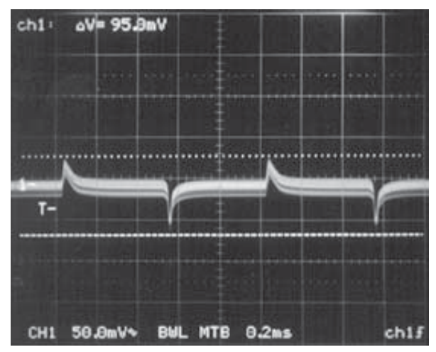
The 550kHz clock frequency and the low 3.3V input voltage allow the use of external inductors in the 1μH range while keeping the ripple current under control. The low inductance value helps in reducing the physical size of the core and raises the attainable dI/dt at the output of the circuit, decreasing the time that it takes for the circuit to correct for sudden changes in load current. This, in turn, reduces the amount of output capacitance required to support the output voltage during a load transient. Figure 2 shows the output voltage transient response for the 2.5V supply subjected to a 0A-5A load step with one 180μF capacitor. Figure 3 shows the output voltage transient response for the 1.8V supply subjected to a 0A-12A load step with three 180μF capacitors. Reduced input capacitance due to the LTC1702’s 2-phase internal switching, combined with its 550kHz clock frequency, significantly reduces the total capacitance needed compared to a conventional switching regulator.

Figure 2. LTC1702 Transient Response for ILOAD = 0A to 5A. VIN = 3.3V, VOUT1 = 2.5V.

Figure 3. LTC1702 Transient Response for ILOAD = 0A to 12A. VIN = 3.3V, VOUT2 = 1.8V.
Figure 4 shows the typical efficiency curves for the LTC1702 circuit of Figure 1. It can be seen from Figure 4 that for the 2.5V supply, efficiency greater than 87% is achievable for load currents of up to 5A; for the 1.8V supply, efficiency greater than 85% is achievable for load currents of up to 12A with peak efficiencies of well over 90%. The circuit in Figure 1 can be laid out in less than 1.5 square inches, and can be easily modified to deliver higher or lower load currents by making a few minor changes to the power path components.

Figure 4. LTC1702 Efficiency Curves. VIN = 3.3V, VOUT1 = 2.5V, VOUT2 = 1.8V
