Few Components Needed for an ESD-Protected Solid-State Potentiometer (EPOT) System with Two Pushbuttons
要約
This design note shows how a simple circuit uses two pushbuttons and three tiny ICs to implement a debounced, ESD-protected solid-state potentiometer (EPOT). The design features the MAX5161digital potentiometer, the MAX6308 programmable reset IC, and the MAX6817 switch debouncer.
A similar version of this article appeared in the September 26, 2002 issue of EDN magazine.
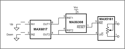
As systems grow smaller, it becomes increasingly attractive to replace mechanical potentiometers with smaller and less expensive silicon equivalents (EPOTs). A common interface for such EPOTs consists of a chip select, increment, and active-low up/down line. CS activates the device, and on a rising edge of active-low INC steps the wiper in a direction indicated by the active-low U/D pin. The simple circuit of Figure 1 employs two pushbuttons (one for up and one for down) and a few tiny silicon devices to implement a debounced, ESD-protected EPOT system.

Figure 1. These three ICs form a solid-state potentiometer (EPOT).
The normally open pushbutton switches feed into an ESD-protected switch debouncer in a SOT23 package (MAX6817) which has internal pullup resistors on the inputs and buffered, non-inverting CMOS outputs. In the absence of a switch closure, the normally open switches hold the MAX6817 outputs high. In turn, that condition ensures a low state for the active-low, push-pull output of the MAX6308; an SC70 reset device with two reset inputs that are independent of the VCC pin. The reset device must have extra reset inputs rather than a manual reset input, because the glitch-immunity protection of MR inputs is not sufficient to guarantee proper operation.
The MAX5161 is a 32-tap, linear-taper EPOT in a SOT23 package, with the standard (active-low INC)-active-low U/D interface. (The CS input is pulled high internally.) Its tsetup requirement is 50ns, meaning the active-low U/D signal must be stable for 50ns preceding a rising edge at the active-low INC pin. That requirement is met with the delay introduced by transient-filtering circuitry internal to the MAX6308. The delay (shown in Figure 2 as tf) is typically 10µs to 30µs. Active-low INC goes high again only after the reset timeout interval expires. For the MAX6308, that interval (treset) is preset at the factory with a value as short as 1ms.

Figure 2. Closing either pushbutton in Figure 1 increments the potentiometer output in a direction indicated by the MAX5161's active-low U/D input.