AN-7597: Using the MAX14906PMB# with TMCM-0960-MotionPy
Introduction
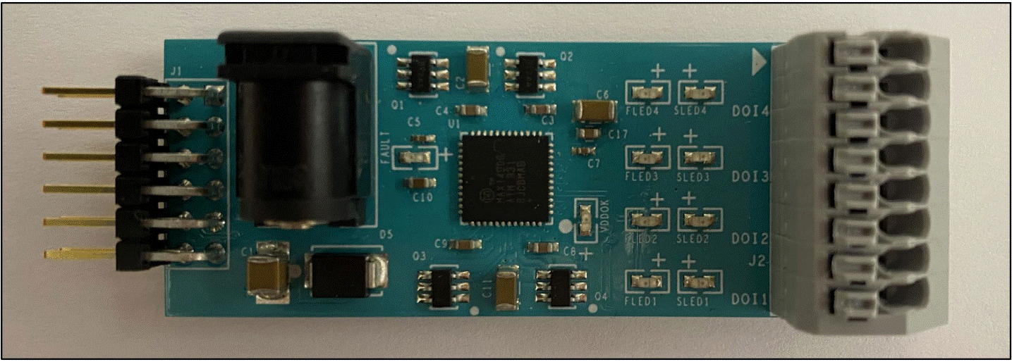
This document introduces the usage of MAX14906PMB# with TMCM-0960-MotionPy V2.1. The MAX14906PMB# is a peripheral module that provides a quick prototype for the MAX14906 industrial digital input/digital output device. This device offers four individually configurable channels as a high-side switch, a push-pull driver, a Type 1/3 digital input, or a Type 2 digital input. For more information, refer to the MAX14906 datasheet and the MAX14906PMB# product page. Basic functions of the MAX14906 are implemented in a MicroPython environment for use on a TMCM-0960-MotionPy board. A brief overview of how to use these basic functions and how to set up the example is provided.

Requirements
- MAX14906PMB#, including a 24V DC power adapter
- USB-C Cable
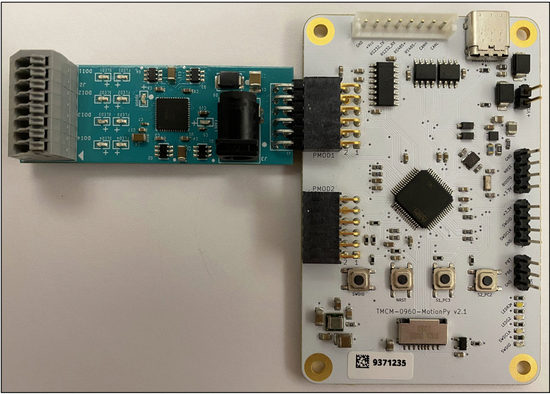
- TMCM-0960-MotionPy V2.1 set up as shown in AN061
- Terminal connection to the TMCM-0960-MotionPy board
Connecting the Pmod™ Board
The MAX14906 communicates with a host controller using an SPI interface, which can be accessed through the PMOD1 and PMOD2 connectors on the TMCM-0960-MotionPy V2.1 board.
The default connection corresponds to the PMOD1 connector as shown in Table 1 and Figure 2, where the MAX14906PMB# is the slave device and the TMCM-0960-MotionPy is the master device. In addition to the four SPI signals (CS, SCLK, MOSI, and MISO), the READY, SYNCH, EN, and FAULT signals can be accessed through the appropriate GPIO pins.

| MAX14906PMB# J1 SIGNALS | MAX14906PMB# J1 PIN NO. (Note 2) | TMCM-0960-MotionPy PMOD1 SIGNALS | TMCM-0960-MotionPy PMOD1 PIN NO. (Note 2) | DESCRIPTION |
|---|---|---|---|---|
| DIO_SPI_SCLK | 4 | SPI1_SCLK | 7 | Serial Clock |
| DIO_SPI_MISO | 3 | SPI1_MISO | 5 | Master Serial Data In, Slave Serial Data Out |
| DIO_SPI_MOSI | 2 | SPI1_MOSI | 3 | Master Serial Data Out, Slave Serial Data In |
| DIO_SPI_CSB | 1 | CS01 | 1 | Chip Select |
| DIO_EN | 10 | GPO3 | 8 | MAX14906 DOI Enable Input |
| DIO_SYNCH | 9 | GPO2 | 6 | MAX14906 SYNCH Control Input |
| DIO_READYB | 8 | GPO1 | 4 | MAX14906 Logic Supply Ready Output |
| DIO_FAULTB | 7 | CS02 | 2 | MAX14906 Diagnostic Fault Output |
Note 1: On the TMCM-0960-MotionPy V2.1 schematic, the Pmod connectors are labeled as PMOD0 and PMOD1, but on the PCB silkscreen they are labeled as PMOD1 and PMOD2. In the Python driver, the connector variables are called pmod1 and pmod2.
Note 2: On the MAX14906PMB#, the connector J1 numbering convention is 1 to 6 for the outside row and 7 to 12 for the inside row. However, on the TMCM-0960-MotionPy V2.1, the Pmod connector numbering convention is 1, 3, 5, 7, 9, 11 on one row and 2, 4, 6, 8, 10, 12 on the other row. Despite the different numbering, the physical signal mapping is consistent.
Structure and Functions
The MAX14906 communicates with a host controller through an SPI interface. SPI initialization, register read/write, and basic configuration and monitoring have been implemented in the max14906.py script. For more information on TMCM-0960-MotionPy and its file system, refer to AN061.
The basic functions read(addr) and write(addr, data) are used to read and write registers in the MAX14906. To set a specific channel to digital output or digital input, set_DO(channel) and set_DI(channel) can be used.
If configured as a digital output, the channels can be switched on or off using static_high_mode(channel) or static_low_mode(channel). The MAX14906 provides four digital output operation modes (high-side mode, high-side with x2 inrush current mode, active push-pull mode, and simple push-pull mode) for each channel, and four different current limits (130mA, 300mA, 600mA and 1.2A) for each channel, which can be configured using high_side_mode(channel), high_side_modex2(channel), push_pull_mode_active(channel), push_pull_mode_simple(channel), and current_lim_set(channel, setCurr). The high_z_mode(channel) function is provided to allow the channel to be configured in the lowleakage high-impedance mode.
If configured as a digital input, DI_type(type) can be used to configure all digital input channels to Type 1/3, or Type 2. For more information, refer to the MAX14906 datasheet.
Note: It is not possible to mix input types as the internal current sink is globally set to either Type 1/3, or Type 2. If Type 2 is chosen, all digital input channels are set to Type 2.
Table 2 contains a full list of functions implemented in the max14906.py. For the complete register map and device features, refer to the MAX14906 datasheet.
| FUNCTION | ARGUMENTS | DESCRIPTION |
|---|---|---|
| read(addr) | addr (hex): valid register address | Reads register contents and verifies CRC. Returns 24-bit binary string. |
| write(addr, data = "00000000") | addr (hex): valid register address data(str): binary string to write to the register | Writes data to register and verifies CRC. Returns 24-bit binary string. |
| set_DO(channel) | channel (int): 1, 2, 3, 4 | Sets specified channel to digital output and set output to low. |
| set_DI(channel) | channel (int): 1, 2, 3, 4 | Sets specified channel to digital input. |
| high_z_mode(channel) | channel (int): 1, 2, 3, 4 | Sets specified channel to high-z mode. |
| static_low_mode(channel) | channel (int): 1, 2, 3, 4 | Sets specified channel to digital output static low. |
| static_high_mode(channel) | channel (int): 1, 2, 3, 4 | Sets specified channel to digital output static high. |
| high_side_mode(channel) | channel (int): 1, 2, 3, 4 | Sets specified channel to DO high-side mode. |
| high_side_modex2(channel) | channel (int): 1, 2, 3, 4 | Sets specified channel to DO high-side mode with 2x inrush current. |
| push_pull_mode_active(channel) | channel (int): 1, 2, 3, 4 | Sets specified channel to DO active push-pull mode. |
| push_pull_mode_simple(channel) | channel (int): 1, 2, 3, 4 | Sets specified channel to DO simple push-pull mode. |
| current_lim_set(channel, setCurr) | channel (int): 1, 2, 3, 4 setCurr (str): "600mA", "130mA", "300mA", "1.2A" | Sets specified channel output current limit to 600mA, 130mA, 300mA, or 1.2A. |
| DI_type(type) | type (int): 1, 2, 3 | Configures digital input type for all channels to Type 1/3 or Type 2. |
| read_DI(channel) | channel (int): 1, 2, 3, 4 | Reads digital input logic level of a specified channel. Returns '0' as logic low or '1' as logic high. |
| SLED_control(enable = 1) | enable (int): 0, 1 | Enables or disables user control of SLEDs. If disabled, SLEDs are controlled autonomously by the MAX14906. |
| set_SLED(LED, val) | LED (int): 1, 2, 3, 4 val (int): 0 (off), 1 (on) | Turns specific SLED LED on or off. |
| FLED_control(enable = 1) | enable (int): 0, 1 | Enables or disables user control of FLEDs. If disabled, FLEDs are controlled autonomously by the MAX14906. |
| set_FLED(FLED, val) | LED (int): 1, 2, 3, 4 val (int): 0 (off), 1 (on) | Turns specific FLED LED on or off. |
| EN(val) | val (int): 0 (disable), 1 (enable) | Drive high to enable all DOI channels. Drive low to disable all DOI channels. |
| SYNCH(val) | val (int): 0 (off), 1 (on) | Drive SYNCH low to prevent DOI outputs from changing and DOI input levels from being updated. Drive SYNCH high to update DOI output states and DOI input status immediately. In DO modes, outputs are updated on rising SYNCH edge. In DO and DI modes, logic levels are read and latched on falling SYNCH edge. |
| enable_fault_latching(latching = 1) | latching (int): 0 (disable), 1 (enable) | Enables or disables latching of diagnostic fault bits, including open-wire faults and short-to-VDD faults. |
| read_global_err() | -- | Reads Global Error register and returns data byte as binary string. |
| check_fault() | -- | Returns True if FAULT signal is asserted and False if FAULT signal is not asserted. |
| enable_OW_fault (channel) | channel (int): 1, 2, 3, 4 | Enables open-wire detection for a specific channel. |
| disable_OW_fault(channel) | channel (int): 1, 2, 3, 4 | Disables open-wire detection for a specific channel. |
| read_OW_fault() | -- | Returns open-wire fault bit for all four channels, with 0 as no fault and 1 as fault. First bit represents channel 4 and last bit represents channel 1. |
| enable_ShVDD(channel) | channel (int): 1, 2, 3, 4 | Enables short-to-VDD detection for a specific channel. |
| disable_ShVDD(channel) | channel (int): 1, 2, 3, 4 | Disables short-to-VDD detection for a specific channel. |
| read_ShVDD_fault() | -- | Returns short-to-VDD fault bit for all four channels, with 0 as no fault and 1 as fault. First bit represents channel 4 and last bit represents channel 1. |
| enable_GDrv(channel) | channel (int): 1, 2, 3, 4 | Enables gate driver for the external PMOS on a specific channel. |
| disable_GDrv(channel) | channel (int): 1, 2, 3, 4 | Disables gate driver for the external PMOS on a specific channel. |
| read_Interrupt() | -- | Returns contents of Interrupt Register as binary string. |
| masking(bit, enable = 1) | bit (int): 0, 1, 2, 3, 4, 5, 6, 7 enable (int): 0, 1 | Masks specified diagnostic fault (enable = 1) from asserting FAULT pin or removes masking (enable = 0). See MAX14906 data sheet for details on which bit corresponds to which fault. |
Running the Example
To begin, use the example script max14906pmb.py. As shown in Figure 2, connect the MAX14906PMB# to the TMCM-0960-MotionPy and a 24V power adapter to the MAX14906PMB# connector J3. Connect the TMCM-0960-MotionPy to the PC using a USB-C cable and start a serial terminal connection. The example script can be executed with the following command:

The example script sets Channel 1 to digital output high-side mode. It toggles DOI1 high or low and turns SLED1 LED on or off every 2.5 seconds. Channel 2 is configured as Type 1/3 digital input and is read every 2.5 seconds. Global errors, open-wire faults, and short-to-VDD faults are enabled and monitored each cycle. The script runs continuously until terminated by the user. The terminal displays the DOI status each cycle, as shown below:

The example has other configurations set up as comments for the user to modify and experiment with.
References/Other Resources
MAX14906:
https://www.maximintegrated.com/en/products/interface/signal-integrity/MAX14906.html
MAX14906PMB#:
https://www.maximintegrated.com/en/products/interface/signal-integrity/MAX14906PMB.html
TMCM-0960-MotionPy V21:
https://www.trinamic.com/products/modules/details/tmcm-0960-motionpy-v21/
TMCM-0960-MotionPy V21 with TMCL-Modules:
https://www.trinamic.com/products/modules/details/tmcm-0960-motionpy/
Trademarks
Pmod is a trademark of Digilent, Inc.