AN-1250: Interfacing an ADT7310/ADT7410 to a Cortex-M3 Based Precision Analog Microcontroller (ADuCM360)
Introduction
This application note describes how to connect evaluation boards and how to easily start collecting high accuracy, digital temperature readings from the ADT7310 and ADT7410 sensors using the Cortex-M3® based precision Analog Devices Inc., microcontrollers, such as the ADuCM360.
This application note also includes example code showing how a microcontroller and temperature sensor can communicate with each other using the I2C and SPI interface. Simple functions to control the ADT7310 and ADT7410 are available.
See the AN-1250 companion code zip file available on the analog.com website.
Interfacing The Evaluation Boards
Analog Devices offers evaluation boards that allow quick prototyping of an application. For example, consider the ADuCM360 (EVAL-ADuCM360QSPZ) and ADT7310 and ADT7410 (EVAL-ADT7x10EBZ) evaluation boards. Figure 1 shows EVAL-ADuCM360QSPZ connected to EVAL-ADT7x10EBZ.

Figure 1. EVAL-ADuCM360QSPZ Connected to EVAL-ADT7X10EBZ.
ADT7310 Evaluation Board
Table 1 lists the signals available on the ADT7310 evaluation board connector for quick prototyping.
| J1 Pin | Signal | Description |
| 1 | VDD | Positive Supply Voltage (2.7 V to 5.5 V). Decouple the supply with a 0.1 µF ceramic capacitor to ground. |
| 2 | GND | Analog and Digital Ground. |
| 3 | SCLK | Serial Clock Input. The serial clock is used to clock in and clock out data to and from any register of the ADT7310. |
| 4 | DOUT | Serial Data Output. Data is clocked out on the SCLK falling edge and is valid on the SCLK rising edge. |
| 5 | DIN | Serial Data Input. Serial data to be loaded to the control registers is provided on this input. Data is clocked into the registers on the rising edge of SCLK. |
| 6 | CS | Chip Select Input. The device is selected when this input is low. The device is disabled when this pin is high. |
Note that it is important to check the microcontroller supply range. For example, the ADuCM360 supply range is 1.8 V to 3.6 V.
Figure 2 shows typical SPI connections between the master and the ADT7310.

Figure 2. An ADuCM360 (Master) with Single ADT7310 (Slave) SPI Block.
ADT7410 Evaluation Board
Table 2 lists the signals available on the ADT7410 evaluation board connector for quick prototyping.
| J1 Pin | Signal | Description |
| 1 | VDD | Positive Supply Voltage (2.7 V to 5.5 V). Decouple the supply with a 0.1 µF ceramic capacitor to ground. |
| 2 | GND | Analog and Digital Ground. |
| 3 | SCL | I2C Serial Clock Input. The serial clock is used to clock in and clock out data to and from any register on the ADT7410 open-drain configuration. A pull-up resistor is required, typically 10 kΩ. |
| 4 | SDA | I2C Serial Data Input/Output. Serial data to and from the part is provided on this pin. Open-drain configuration. A pull-up resistor is required, typically 10 kΩ. |
| 5 | A0 | I2C Serial Bus Address Selection Pin. Logic input. Connect to GND or VDD to set an I2C address. |
| 6 | A1 | I2C Serial Bus Address Selection Pin. Logic input. Connect to GND or VDD to set an I2C address. |
Note that it is important to check the microcontroller supply range. For example, the ADuCM360 supply range is 1.8 V to 3.6 V.
Figure 3 shows typical I2C connections between the master and the ADT7410.

Figure 3. An ADuCM360 (Master) with Single ADT7410 (Slave) I2C Block.
External pull-up resistors are recommended on the SCL and SDA lines. The ADuCM360 typically has internal pull-ups on GPIOs that can be disabled in software when using the I2C bus. The companion code demonstrates how to disable the internal pull-ups.
ADUCM360 Evaluation Board
The ADuCM360 evaluation boards are mini boards with all GPIOs available on the edge connectors. Table 3 shows example connections for the ADuCM360.
| J1 Pin | Signal | Description |
| 3 | DVDD | Positive Supply Voltage (1.8 V to 3.6 V). |
| 4 | DGND | Digital Ground. |
| 17 | P1.4 | SPI0 Port: MISO. |
| 18 | P1.5 | SPI0 Port: SCLK. |
| 19 | P1.6 | SPI0 Port: MOSI. |
| 20 | P1.7 | SPI0 Port: CS. |
| 21 | P2.0 | I2C Port: SCL. |
| 22 | P2.1 | I2C Port: SDA. |
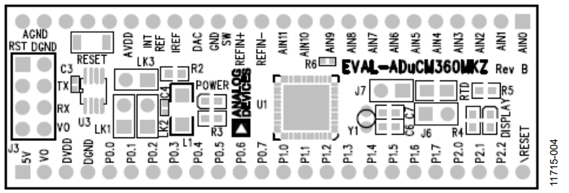
Figure 4. ADuCM360 Top Side View.
Companion Code
Typically, a project contains three source files and two definition files to interface the temperature sensors to the ADuCM360. Table 4 lists these files.
| Source and Definitions | Description |
| ADT7410I2C.c | Set of functions to interface the ADuCM360 to ADT7410 via I2C |
| ADT7410I2C.h | Functions and parameters definitions to interface the ADuCM360 to ADT7410 via I2C |
| ADT7310SPI.c | Set of functions to interface the ADuCM360 to ADT7410 via SPI |
| ADT7310SPI.h | Functions and parameters definitions to nterface the ADuCM360 to ADT7410 via SPI |
| ADT7x10_Demo.c | Example code that calls some of the functions |
Using The Demo COD
After connecting the boards, download code to the ADuCM360 and open a serial port terminal application, such as HyperTerminal®.
Check the UART setting (9600 bps). Figure 5 shows the results on the serial port.

Figure 5. Results on Serial Port.
Demo Code Flowchart
Figure 6 shows the demo code flowchart. The demo code configures the sensors in continuous conversion mode. In continuous mode, a new result is available every 240 ms.

Figure 6. Demo Code Flow Chart.
A software delay is used between each request for a temperature measurement result. This software delay can be replaced with the timer periodically interrupting the ADuCM360 to read the sensors measurements.
Interface Functions
Table 6 lists all functions included in the ADT7410I2C and ADT7310SPI files.
ADT7310 Functions
These five functions cover the main features of the ADT7310. Parameters for these functions are defined in the header file (ADT7310SPI.h). All functions are based on the SPI low-level functions of the ADuCM360. Note that some of the microcontrollers may have more than one SPI. The AN-1248 Application Note, SPI Interface, provides general information on SPI.
The maximum SPI speed of the ADT7310 is 5 Mbps. For more information on the ADT7310 features, consult the ADT7310 data sheet.
ADT7410 Functions
These five functions cover the main features of the ADT7410. Parameters for these functions, including the sensor address, are defined in the header file (ADT7410I2C.h). All functions are based on the I2C low-level functions described in the AN-1159 Application Note, I2C-Compatible Interface on Cortex-M3 Based Precision Analog Microcontroller (ADuCxxx Family).
For more information on the ADT7410 features, consult the ADT7410 data sheet.
| Function Name | Function Description |
| int ADT7310_SPICFG (int Resolution, int iMode, int CT, int INT, int INTCTmode, int Fault_queue); | Configure the temperature sensor resolution, mode, CT pin polarity, INT pin polarity, and so on. |
| int ADT7310_SPI_T_Setpoint (int REG_Address, int value); | Configure one of the four set point register (THIGH,TLOW, TCRIT, or THYST). |
| float ADT7310_SPIGetTemperature (void); | Return temperature measurement in °C. |
| long ADT7310_SPI_Status (char REG_Address); | Return content of the register at REG_Address (status, configuration, ID, or T_setpoint). |
| int ADT7310_Reset (void); | Reset the ADT7310. |
| Function Name | Function Description |
| int ADT7410_I2CCFG (char Address, int Resolution, int iMode, int CT, int INT, int INTCTmode, int Faultqueue); | Configure the temperature sensor resolution, mode, CT pin polarity, INT pin polarity, and so on. |
| int ADT7410_I2C_T_Setpoint (char BusAddress, char REGadd, int RorW, int Value); | Configure or read back one of the four set point register (THIGH,TLOW, TCRIT, or THYST). |
| float ADT7410_I2CGetTemperature (char Address, unsigned char *Status, unsigned char *Config); | Return temperature measurement in °C. This function also updates the status and configuration variables. |
| int ADT7410_I2CID (char Address); | Return sensor ID |
| int ADT7410_I2CReset (char Address) | Reset the ADT7410. |
Limitations
This application note does not cover all features of the ADT7310 and ADT7410, such as the over and under temperature detection, because the evaluation boards do not easily allow access to the INT and CT outputs.
著者
