AN-1235: AC Signal Processing Using the AD5450/AD5451/AD5452/AD5453 Current Output DACs
Circuit Function and Benefits
This circuit provides two-quadrant signal multiplication using a AD5450, AD5451, AD5452, or AD5453 current output digitalto-analog converter (DAC) and an AD8038 operational amplifier. It provides a multiplying bandwidth of up to 12 MHz, allowing the user to accurately condition ac signals with bandwidths up to this frequency. The circuit is well suited for ac signal conditioning applications in the communications, industrial, and medical market segments.
Circuit Description
| Product | Description |
| AD5450/AD5451/AD5452/AD5453 | 8-/10-/12-/14-bit multiplying DAC |
| AD8038 | Low power, high performance amplifier |
Figure 1 shows a typical application circuit configuration for a current output multiplying DAC in an ac signal processing application. Using the AD8038 op amp, the AD5450, AD5451, AD5452, or AD5453 DAC can easily be configured to provide a two-quadrant multiplying operation or a unipolar output voltage swing. The AD5450/AD5451/AD5452/AD5453 are CMOS 8-/ 10-/12-/14-bit current output DACs, respectively. These devices operate from a VDD power supply of 2.5 V to 5.5 V, making them suited to battery-powered applications and many other applications that include signal attenuation, channel equalization, and waveform generation. The AD8038 is a high speed, voltage feedback amplifier with an exceptionally low quiescent current and operates with a VDD1 supply of +5 V and a VSS of −5 V, providing a high slew rate of 425 V/µs and is used as the current-to-voltage converter in this circuit. With the configuration used in Figure 1, the output voltage is given by
VOUT = −VIN × (D/2N)
where:
VIN is applied to the reference input of the DAC and is an ac input signal in this configuration.
D is the digital word loaded to the DAC, and D = 0 to 255 (8-bit AD5450), D = 0 to 1023 (10-bit AD5451), D = 0 to 4095 (12-bit AD5452), and D = 0 to 16,383 (14-bit AD5453).
N is the DAC resolution.

Figure 1. AC Signal Processing Configuration Using a Multiplying Current Output DAC (Simplified Schematic: Decoupling and All Connections Not Shown).
Common Variations
The compensation capacitor, CC, used in the circuit controls the dynamic performance of the circuit effectively determining the circuit settling and output overshoot characteristics. Figure 2 shows the measured ac multiplying bandwidth of the circuit shown in Figure 1. This is essentially the frequency response of the DAC when an ac reference is applied to its reference input pin. Figure 2 shows that multiplying bandwidths of up to 12 MHz have been achieved.
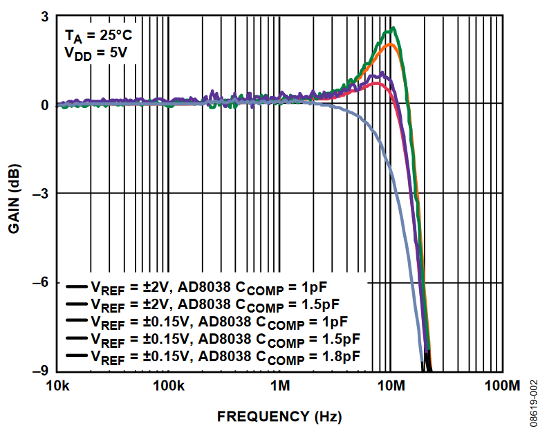
Figure 2. AC Multiplying Bandwidth Performance.
In any circuit where ac performance is important, careful consideration is given to the layout to ensure that the rated performance is achieved. Design the printed circuit board (PCB) so that the analog and digital sections are separated and confined to certain areas of the board. If the DAC is in a system where multiple devices require an AGND-to-DGND connection, make the connection at one point only. Establish the star ground point as close as possible to the device.
These DACs must have ample supply bypassing of 10 µF in parallel with 0.1 µF on the supply located as close to the package as possible, ideally right up against the device. The 0.1 µF capacitor must have low effective series resistance (ESR) and low effective series inductance (ESL), like the common ceramic types that provide a low impedance path to ground at high frequencies, to handle transient currents due to internal logic switching. In addition, apply low ESR, 1 µF to 10 µF tantalum capacitors at the supplies to minimize transient disturbance and filter out low frequency ripple.
To optimize high frequency performance, locate the I-V amplifier as close to the DAC as possible. The inclusion of a compensation capacitor, CC, influences the overshoot and settling time characteristics of the circuit, as shown in Figure 2. Figure 61 to Figure 64 in the AD5450/AD5451/AD5452/AD5453 data sheet show the schematics and layout used for this circuit.
LEARN MORE
Kester, Walt. The Data Conversion Handbook. Chapter 3, 7. Analog Devices. 2005.
MT-015 Tutorial, Basic DAC Architectures II: Binary DACs. Analog Devices.
MT-031 Tutorial, Grounding Data Converters and Solving the Mystery of AGND and DGND. Analog Devices.
MT-033 Tutorial, Voltage Feedback Op Amp Gain and Bandwidth. Analog Devices.
MT-035 Tutorial, Op Amp Inputs, Outputs, Single-Supply, and Rail-to-Rail Issues. Analog Devices.
MT-101 Tutorial, Decoupling Techniques. Analog Devices.
ADIsimPower Design Tool. Analog Devices.
Voltage Reference Wizard Design Tool, Analog Devices.