資料ライブラリ
AN-1218: Compact, Low Cost, 5 V, Variable Gain, Noninverting Amplifier Using the AD5270/AD5272 Digital Rheostat and AD8615 Op Amp
Circuit Function and Benefits
This circuit shown in Figure 1 provides a compact, low cost, low voltage, variable gain noninverting amplifier using the AD5270/ AD5272 digital rheostat in conjunction with the AD8615 operational amplifier. The small package sizes of the AD5270/ AD5272 (10-lead 3 mm × 3 mm × 0.8 mm LFCSP) and the AD8615 (5-lead TSOT-23), as well as their low cost, present an industry leading solution to a common analog signal processing circuit.
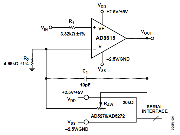
Figure 1. Variable Gain Noninverting Amplifier (Simplified Schematic: Decoupling and All Connections Not Shown).
The circuit offers 1024 different gains, controllable through an SPI (AD5270) or I2C-compatible (AD5272) serial digital interface. The ±1% resistor tolerance performance of the AD5270/AD5272 provides low gain error over the full resistor range, as shown in Figure 2.

Figure 2. R2 Value Range vs. Minimum Input Signal.
The circuit supports rail-to-rail inputs and outputs for both single-supply operation at +5 V and dual-supply operation at ±2.5 V and is capable of delivering up to ±150 mA output current.
In addition, the AD5270/AD5272 has an internal 50-times programmable memory that allows a customized gain setting at power-up.
The circuit provides accuracy, low noise, and low THD and is well suited for signal instrumentation conditioning.
Circuit Description
| Product | Description |
| AD5270/AD5272 | 10-bit, 1% resistor tolerance digital rheostat |
| AD8615 | Precision, 20 MHz, CMOS, rail-to-rail input/output CMOS op amp |
The circuit employs the AD5270/AD5272 digital rheostat in conjunction with the AD8615 CMOS operational amplifier, providing a low cost, compact, variable gain noninverting amplifier.
The input signal, VIN, is amplified by the AD8615. The op amp offers slow noise, high slew rate, and rail-to-rail inputs and outputs.
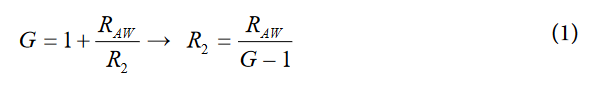
The maximum circuit gain is defined in Equation 1.
The maximum allowable current through the AD5270/AD5272 (RAW = 20 kΩ version) is ±3 mA, which limits the maximum input voltage, VIN, based on the circuit gain as described in Equation 2.

When the input signal, VIN, is higher than the theoretical maximum value from Equation 2, R2 should be increased, and the new gain can be recalculated using Equation 1.
On the other hand, the minimum gain should be calculated to reduce the error due to the leakage current in the AD5270/ AD5272. To assume a negligible leakage current error, the current through R2 should be at least 100 times the worst-case leakage specification of 50 nA . Therefore, the minimum current through R2 should be 5 µA, which defines the minimum value for R2, as in Equation 3.

Figure 2 shows the possible R2 value range based on the input voltage to the op amp, assuming these conditions.
The ±1% internal resistor tolerance of the AD5270/AD5272 ensures a low gain error, as shown in Figure 3.

Figure 3. Gain and Gain Error vs. Decimal Code.
The circuit gain equation is:
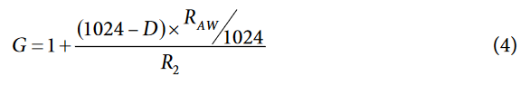
where D is the code loaded in the digital potentiometer.
When the circuit input is an ac signal, the parasitic capacitances of the digital potentiometer can cause undesirable oscillation in the output. This can be avoided, however, by connecting a small capacitor, C1, between the inverter input and its output. A value of 10 pF was used for the gain and phase plots shown in Figure 4.
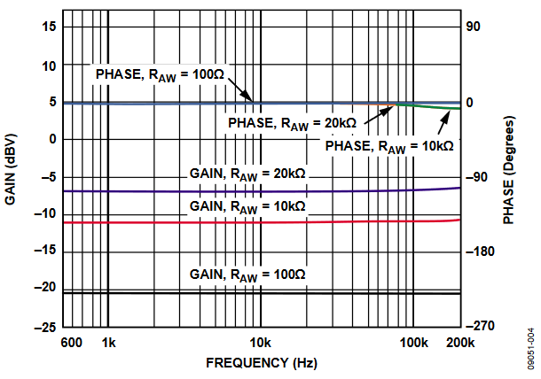
Figure 4. Gain and Phase vs. Frequency for the AC Input Signal (Vertical Scale Compressed to Show All Gain Curves).
The AD5270/AD5272 have a 50-times programmable memory, which allows presetting the output voltage in a specific value at power-up.
Excellent layout, grounding, and decoupling techniques must be used to achieve the desired performance from the circuits discussed in this note (see Tutorial MT-031, Grounding Data Converters and Solving the Mystery of “AGND” and “DGND” and Tutorial MT-101, Decoupling Techniques). As a minimum, a 4-layer PCB should be used with one ground plane layer, one power plane layer, and two signal layers.
Common Variations
The AD5271/AD5274 (8-bits with 50-times programmable power-up memory) are both ±1% tolerance digital rheostats that are suitable for this application if 10-bit resolution is not required.
The same basic circuit shown in Figure 1 can be adapted to operate on a 30 V supply using higher voltage devices as described in the CN-0112 Circuit Note.
References
MT-031 Tutorial, Grounding Data Converters and Solving the Mystery of "AGND" and "DGND," Analog Devices.
MT-032 Tutorial, Ideal Voltage Feedback (VFB) Op Amp, Analog Devices.
MT-087 Tutorial, Voltage References, Analog Devices.
MT-091 Tutorial, Digital Potentiometers, Analog Devices.
MT-101 Tutorial, Decoupling Techniques, Analog Devices.