AN-1121: Replacing Mechanical Potentiometers with Digital Potentiometers
Introduction
Potentiometers have been widely used since the early days of electronic circuits, providing a simple way to calibrate a system, adjusting offset voltage or gain in an amplifier, tuning filters, controlling screen brightness, among other uses. Due to their physical construction, mechanical potentiometers have some limitations inherent to their nature, such as size, mechanical wear, wiper contamination, resistance drift, sensitivity to vibration, humidity, and layout inflexibility.
Digital potentiometers are designed to overcome all these problems, offering increased reliability and higher accuracy with smaller voltages glitches. The mechanical potentiometer has now been relegated to environments where the digital potentiometer cannot be a suitable replacement, such as high temperature environments or in high power applications.
Comparing both technologies is the simplest way to discern which is the optimal solution for your system.
Architecture
Mechanical Potentiometer
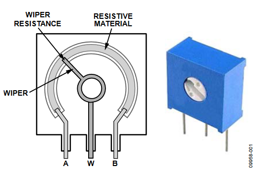
The mechanical potentiometer is formed by a large resistive element that is connected externally by two terminals. The resistive element can be found in different forms, wrapped inside the package; depending on the technology, this wrap can be a single turn or multiple turns, or simply flat.
A third terminal, called the wiper, can be moved through the entire resistive element to select the resistance between each external terminal and the wiper. There is a small contact resistance between the wiper and the resistive element, called wiper resistance, as shown in Figure 1.

Figure 1. Mechanical Potentiometer.
Digital Potentiometer
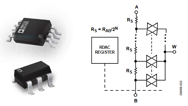
The digital potentiometer is formed by an array of resistive elements; the extremes of this array are bonded to the exterior by two terminals, A and B. In each junction of the two passive resistors, there is a switch. The switches are connected together at a single point, bonded to an external terminal, called the wiper, or W, as shown in Figure 2.

Figure 2. Digital Potentiometer.
The switches are designed in a complementary metal-oxide semiconductor (CMOS) process to allow the current to flow in any direction. These are controlled by a digital block and only one switch is on at a time. The parasitic switch resistance is called, by analogy with the mechanical potentiometer, wiper resistance.
Architecture Summary
Due to its physical construction, a mechanical potentiometer is more sensitive to physical environmental changes such as vibration, shocks, and wiper contamination. Alternatively, digital potentiometers remain unchanged under all these conditions due to their monolithic construction.
Adjustment
Mechanical Potentiometer
The mechanical potentiometer theoretically offers infinite resolution because the wiper can move through the entire resistance, but physical factors (for example, screwdriver pressure or material friction) adjusting the resistance add inaccuracy and low precision in the final value.
Note that the maximum number of readjustments, or mean time between failures (MTBF), is typically limited to less than several thousand times.
Digital Potentiometer
The wiper position is determined by the RDAC register content, which has no limitation on the number of writes. The RDAC register can be written using digital interfaces such as SPI, I2C, or up/down, or manually with push-button switches or digital encoders, as shown in Figure 3 and Figure 4.

Figure 3. Push-Button Interface.

Figure 4. Up/Down Interface Controlled with a Digital Encoder.
Digital potentiometers, similar to mechanical potentiometers, have the possibility to restore the RDAC code, previously adjusted, at power-up. Analog Devices, Inc., digital potentiometers offer three different memory technologies: fuses, EEPROM, and volatile digital potentiometers.
Fuses
Analogous to placing epoxy on a mechanical potentiometer, fuses are ideal for a set-and-forget system calibration. Analog Devices offers from 1 up to 50 times the programmable fuse memory.
EEPROM
Offering endurance of up to 1 million cycles and 100 years data retention, an EEPROM is ideal for systems that need to retain the last programmed value, for example, volume control applications.
Volatile
The RDAC register is loaded by default at midscale and does not maintain the resistance if the supply is disconnected. Volatile digital potentiometers are ideal for dynamic systems in which the system recalibrates the output continuously and it is not necessary to restore the previous value, or when a controller is available to set the value at power-up/reset.
Resistive Element
Mechanical Potentiometer
The resistive element can be built from different materials such as cermet, graphite, or conductive plastic, offering a wide range of resistor options from tens of ohms up to mega ohms, which is guaranteed over a specific error range.
This error is known as resistor tolerance and fluctuates depending on the quality of the material and the process used to build the potentiometer. Typical values are in the range of ±30% to ±10% and can be as low as ±3% in higher quality potentiometers.
A second error is due to the dependency of the resistive element with temperature. This dependency is larger or smaller, depending on the material, and the final resistor value changes proportionally with temperature. This error is called temperature coefficient, or TempCo.
Newer materials like wire wound, offering a TempCo down to 10 ppm/°C, whereas the older mechanical potentiometers, constructed using graphite, show a high temperature dependency up to 500 ppm/°C.
Depending on the material, there are associated limitations, such as the maximum power dissipation, which can be from several milliwatts up to hundreds of watts. In all the cases, the voltage between the resistor extremes is proportional to the power. This voltage spreads from tens of volts, up to hundreds of volts, or even kilovolts.
In general, mechanical potentiometers offer higher ratings in terms of voltage and current, but this is inversely proportional to the ambient temperature. The designer should verify that the potentiometer can handle the maximum estimated power in the design, based on the expected maximum temperature in the final application.
Table 1 shows a quick reference of all these characteristics of mechanical potentiometers based on the material used in the construction.
| Characteristic | Material | |||
| Cermet | Graphite | Conductive Plastic | Wire Wound | |
| Tolerance | High | High | Medium | Low |
| TempCo | High | Very high | High | Low |
| Power | Medium | Medium | Medium | High |
| Price | Low to medium | Low | High | High |
Digital Potentiometer
Analog Devices offers the widest portfolio of resistor values, from 1 kΩ up to 1 MΩ.
The resistor tolerance error was previously ±20%; however, this value has been reduced and Analog Devices now offers ±8% tolerance error or a calibrated precision resistance of ±1% tolerance error.
In addition, digital potentiometers with nonvolatile EEPROM typically store the tolerance error, which can be read back by the controller and used to calibrate the resistance externally.
The temperature dependency, TempCo, at any given code depends on two components: the resistive element and the switch resistance. The switch resistance is small, but at lower codes when the selected resistance is small, too, the switch resistance becomes significant because the value is similar. The number of codes affected for the switch resistance TempCo depends directly on the nominal resistor value; a typical TempCo value in this region is around 600 ppm/°C.
For the resistive element, there are two main materials, polysilicon or thin film metal. The polysilicon is the common material and, similar to the graphite, offers the higher dependency on temperature, up to 600 ppm/°C. The thin film metal resistance offers lower temperature coefficients, with values around 35 ppm/°C. Analog Devices data sheets include a graph showing the TempCo at any given code.
The digital potentiometer offers low power dissipation, which is limited up to tens of milliwatts due to its small size. In comparison to the mechanical potentiometers, this power is constant across all temperature ranges. The maximum voltage in the terminal is limited to the supply rails in the digital potentiometer. This can be from 2.3 V up to 33 V depending on the digital potentiometer. However, in all cases, the maximum current typically does not exceed a few milliamperes.
Additional Specifications
With digital potentiometers, the switches introduce some specifications that are not relevant for mechanical potentiometers.
Due to the parasitic capacitance in the switches, there is a bandwidth limitation. This defines the maximum signal frequency that can cross the resistance terminals with <3 dB attenuation in the wiper. The transfer equation is similar to a low-pass filter.
The capacitance does not depend on the nominal resistance selected; it depends only on the internal switch design. Therefore, higher bandwidths can be achieved using low nominal resistor values. Table 2 shows an example.
| Nominal Resistance | 1 kΩ | 10 kΩ | 50 kΩ | 100 kΩ |
| Maximum frequency | 5 MHz | 600 MHz | 125 kHz | 71 kHz |
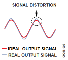
The nonlinearity in the wiper resistance adds a harmonic distortion. The total harmonic distortion, or THD, quantifies the degree to which the signal is degraded after crossing through the resistance. Figure 5 shows a magnified example.

Figure 5. THD Effect.
As an example, if the THD is −80 dB, the signal is degraded 10−80/20 = 0.1 mV/VIN; therefore, if the signal is 1 V p-p, the total signal distortion is 0.1 mV × 2 = 0.2 mV.
Digital potentiometers offer a THD performance from −60 dB up to −106 dB, making them suitable for audio applications.