AN-1080: Power-Up and Power-Down Sequencing Using the ADM108x Simple Sequencer
Introduction
The ADM108x simple sequencer can achieve simple sequencing for two voltage rails during power-up with capacitor programmable time delay. With the help of another device in the same family, a simple circuit can achieve sequencing for both power-up and power-down for two voltage rails with separate programmable time delay, as shown in Figure 1. This application note describes how to design such a circuit.
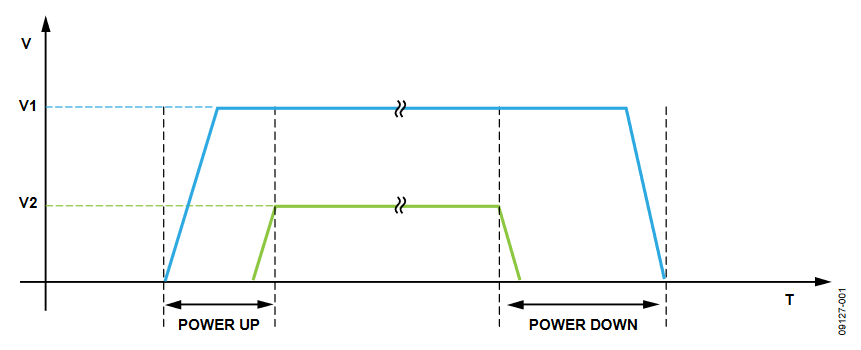
Figure 1. Typical Sequencing Requirement for Power-Up and Power-Down.
Implementation
Circuit Design
Figure 2 shows the block diagram of the circuit. The main components of the circuit consist of two power regulators, an N-type signal MOSFET, an ADM1085, and an ADM1087. This circuit supports most dc-to-dc regulators with enable input.
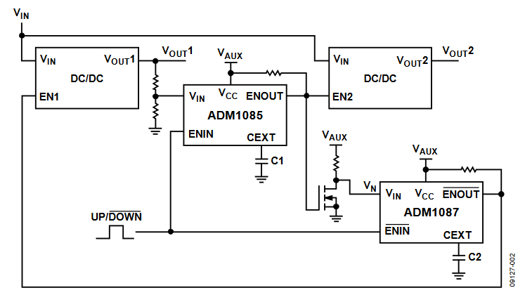
Figure 2. Circuit Block Diagram.
The resistor divider at the input of the ADM1085 is used to accurately monitor the first supply output, VOUT1. It ensures that the first supply powers on before enabling VOUT2, which is the second supply output. Alternatively, the VIN pin of the ADM1085 can connect directly to the power good output of the first regulator, if available.
During power-up, C1 controls the time delay between VOUT1 and VOUT2, and during power-down, C2 controls the time delay between VOUT2 and VOUT1.
An auxiliary supply, VAUX, is used to provide power separately for the sequencing circuit. This can be substituted by VIN and the details of the effect are described in the Timing Diagram section.
The initiation of the power-up and power-down sequencing is controlled by the UP/DOWN logic signal.
Timing Diagram
Figure 3 is an overview of the timing diagram for the circuit. It consists of three phases: initial power-up, power-up sequencing, and power-down sequencing.
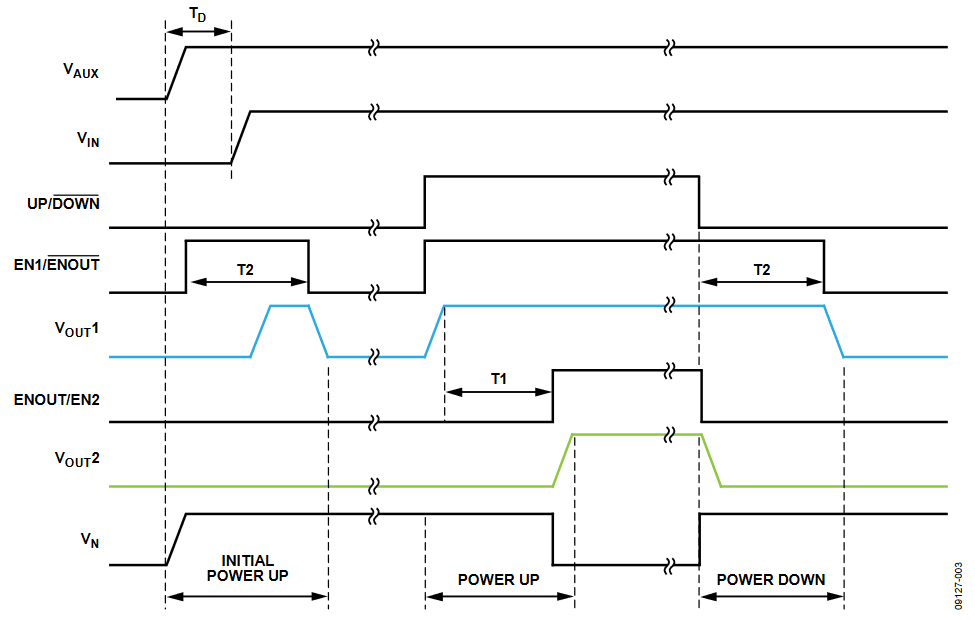
Figure 3. Circuit Timing Diagram.
During the initial power-up phase, the UP/DOWN signal is kept low. After VAUX goes high, the ENOUT output of the goes high for the duration of T2, which is controlled by C2, and then goes low. During this period, the first regulator may be briefly enabled because EN1 is tied to ADM1087 ENOUT. The duration of the first regulator being enabled during the initial power-up phase, TON, is dependent on TD, the power-up delay between VAUX and VIN, and T2 with the relationship TON = T2 − TD.
If TD > T2, for example, VAUX is powered up more than T2 seconds before VIN, then the first regulator is not enabled during the initial power-up phase. If the user chooses to substitute VAUX for VIN, then TD is zero, and the regulator enables for the T2 duration during the initial power-up phase.
In a system where a brief pulse of the first supply, during initial power-up, does not cause any problems, it is recommended to use VIN only for the circuit supply.
Another option is for the user to tie the UP/DOWN signal to VIN, in which case, the first regulator turns on autonomously after VIN rises, and the second regulator is enabled T2 seconds after the output of the first regulator becomes good.
In the power-up sequencing phase, the sequencing is initiated by pulling UP/DOWN high, which causes ENOUT of the ADM1087 to go high and thus enables the first regulator. When the output of the first regulator is detected by the VIN pin of the , its ENOUT pin goes high after T1 seconds to enable the second regulator. T1 is controlled by C1, which creates a programmable delay between the two output voltages, VOUT1 and VOUT2, during power-up. In this phase, the sequencing method is standard usage of the ADM108x simple sequencer.
During the power-down sequencing phase, the sequencing is initiated by the UP/DOWN signal being pulled low. The immediate effect of this is that the ENIN pin of the ADM1085 goes low, and thus, so does its ENOUT pin. This disables the second regulator through the EN2 pin as well as turns off the NMOSFET by driving its gate low. When the FET is off, the VIN pin of the ADM1087 goes high, and because ENIN is already low, after T2 seconds its ENOUT output will go low, turning off the first regulator through EN1. C2 controls T2, which creates a programmable delay between the two output voltages, VOUT2 and VOUT1, during power-down.
Verification
Schematic
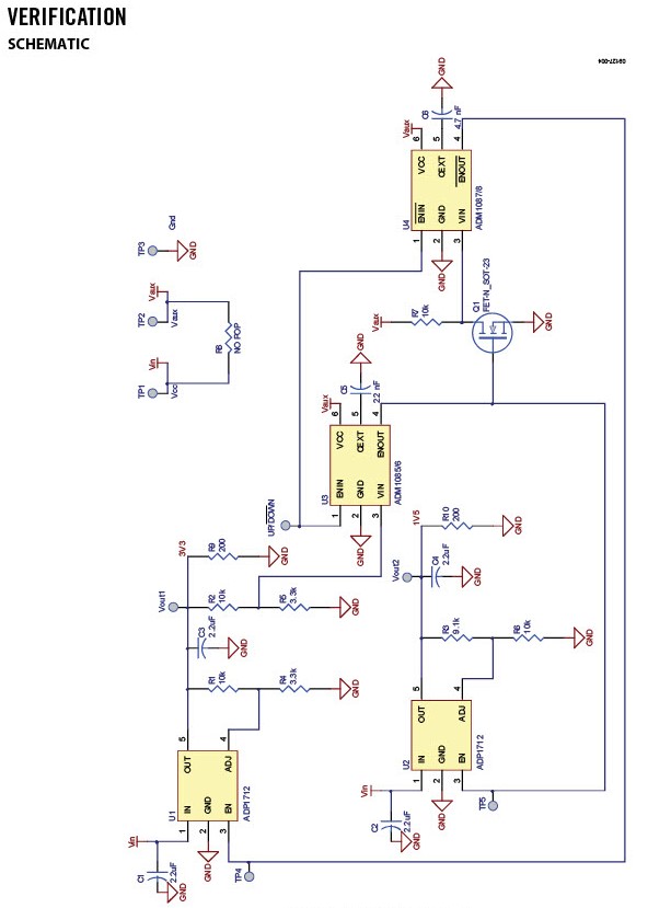
Figure 4. Schematic for Verification Circuit.
TEST RESULTS
Channel 1: VOUT1 (gold), Channel 2: VOUT2 (pink), Channel 3: UP/DOWN (blue), and Channel 4: VIN (green).
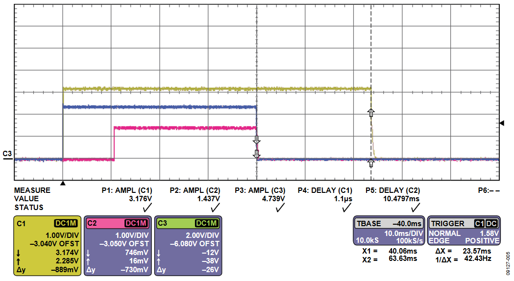
Figure 5. Test Plot Overview.
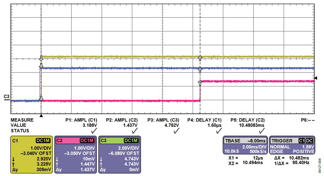
Figure 6. Close-Up Look at the Power-Down Phase.
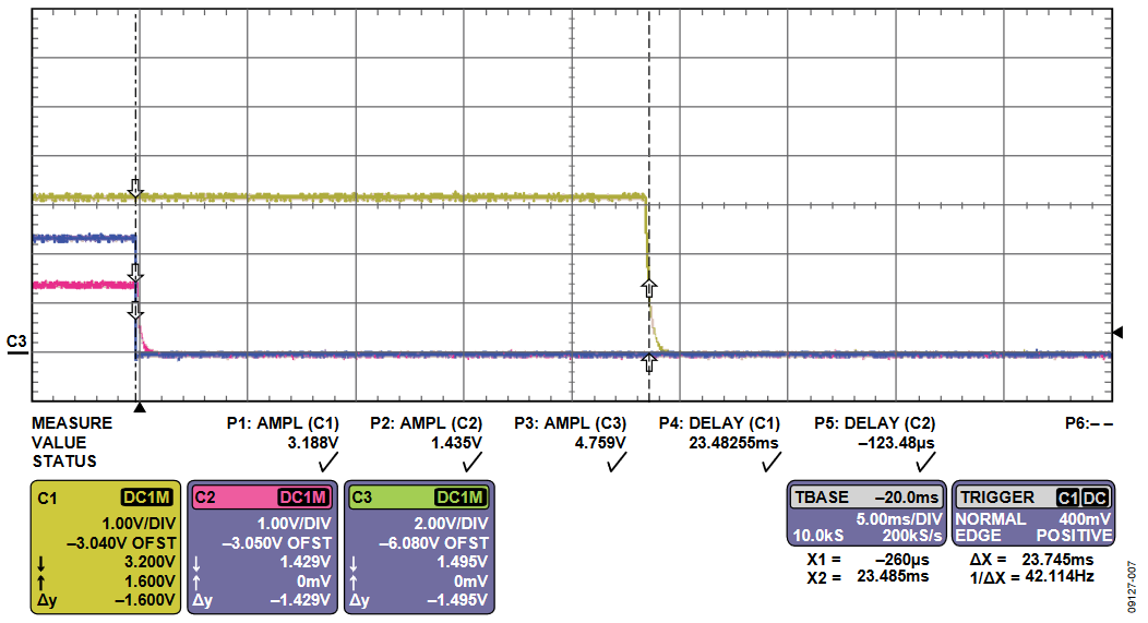
Figure 7. Close-Up Look at the Power-Up Phase.
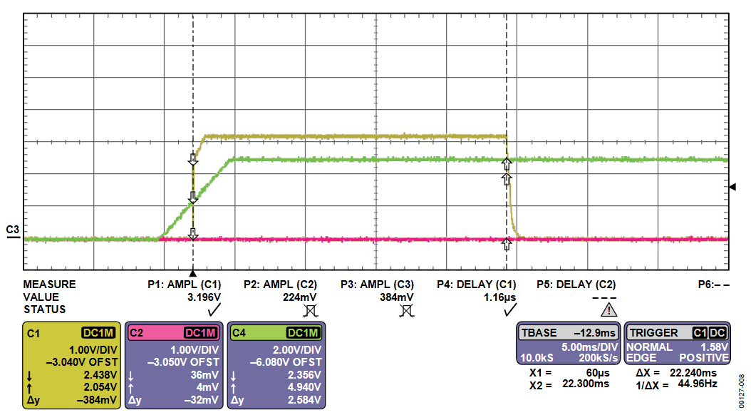
Figure 8. Initial Power-Up Phase.
