概要
本稿では、「LTspice®」上で作成した回路図に電圧制御スイッチ(Voltage-controlled Switch)を追加する方法を詳しく説明します。また、同スイッチの使用方法に焦点を絞ったトランジェント・シミュレーションの例を紹介します。LTspiceは、アナログ回路の設計に役立つシミュレーション用ソフトウェアです。
はじめに
電圧制御スイッチは、LTspiceで使用できる基本的な回路素子の1つです。特に、シミュレーションの途中で変更可能な回路に、オープン・サーキット/ショート・サーキットの振る舞いを簡単に追加したい場合に役立ちます。細部にわたって回路図を改良していくにつれ、FETやスイッチのより精密なモデルを組み込むことが必要になるかもしれません。ただ、初期の段階では、それよりシンプルな電圧制御スイッチを使用するだけで十分なケースも多いでしょう。
回路図の作成方法
まずは、電圧制御スイッチを使用する回路図の作成方法について詳しく説明します。その作業内容は、4つのステップから成ります。なお、本稿は、読者がLTspiceの使用方法に関する基本的な知識を有していることを前提としています。LTspiceの基本について知りたい方は、「Getting Started with LTspice(LTspiceのスタートアップ・ガイド)」とビデオ・シリーズ「LTspice Basics(LTspiceの基礎)」を参照してください。
【ステップ1】電圧制御スイッチのシンボルを配置する
まずは、電圧制御スイッチを追加したい回路図を開きます。あるいは、「File」→「New Schematic」を順に選択し、回路図を新たに作成してください。
「Edit」→「Component」を選択(または「P」を押す)します。コンポーネントのライブラリの画面が開くので、表示される多数の候補の中から「sw」を選択してください(図1)。そのシンボルの向きは、「Rotate」(「CTRL」+「R」)コマンドと「Mirror」(「CTRL」+「E」)コマンドを使用することで微調整できます。「Place」ボタンを押し、回路図上の任意の点をクリックすることで、新たな電圧制御スイッチが配置されます。


【ステップ2】.modelディレクティブを追加する
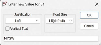
「Edit」→「SPICE directive」を順に選択(または「.」を押す)し、電圧制御スイッチ用の.modelディレクティブを追加します(図2)。まずは入力フィールドに、以下の例のとおりに入力してください。
.model MYSW SW()
ここで、「MYSW」はこの.modelディレクティブに割り当てられた名前です。また、「SW()」は、これが電圧制御スイッチのモデルであることを表しています。モデルのパラメータには、図2に示したようにデフォルトの値が適用されます。「OK」ボタンをクリックし、回路図上の任意の点をクリックすることによって.modelディレクティブを配置します。なお、電圧制御スイッチの.modelディレクティブについて詳しく知りたい方は「Help」→「LTspice Help」を選択してください。「Voltage Controlled Switch」を検索すれば、「SW()」の.modelディレクティブに同スイッチに関する詳細を記述するためのヘルプ情報を参照することができます。


【ステップ3】電圧制御スイッチと.modelディレクティブを結び付ける
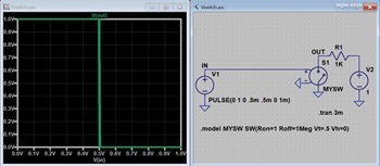
回路図に.modelディレクティブを追加したら、そのモデルと新たな電圧制御スイッチのシンボルを正しくリンク付けします。同スイッチの値(value)には、同スイッチを配置したときにデフォルトで「SW」が設定されています。そこで、値を右クリックし、「SW」を「MYSW」に変更してください(図3)。それにより、この電圧制御スイッチが、新たに作成した「MYSW」のモデルに正しくリンク付けされます。

【ステップ4】制御用の電圧源を追加する
電圧制御スイッチのオン/オフ制御に使用する電圧源を追加します。そのための手順としては、まず「Edit」→「Component」を順に選択します。次に、コンポーネントのダイアログを使用して電圧源を選択してください。その上で「Place」をクリック(または「V」を押す)し、回路図上の任意の点をクリックして電圧源を配置します。
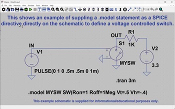
次に、「V」の値を右クリックし、三角波を生成するための設定を行います。具体的には、以下のPULSEコマンドを入力します。
PULSE(-1 1 0 .5m .5m 0 1m)


その結果、図4のような回路図が得られます。電圧制御スイッチの閾値はデフォルトでは0Vです。上記の例の三角波は、50%のデューティ・サイクルでそのデフォルトのモデルをオン/オフ制御します。
簡単なサンプル
ここからは、電圧制御スイッチを使用するシンプルな例を紹介していきます。こちらをクリックしてファイルをダウンロードしてください。このファイルは、「File」→「Open Examples」→「Educational」→「Vswitch.asc」を順に選択することによって開くこともできます(図5)。

シミュレーション結果のプロットを簡素化し、VhとVtの値を変更した場合の影響を明示するために、V2の電圧を1Vに変更します。「3.3」という値を右クリックして「1」に変更してください。
その状態で「Simulate」→「Run」を選択し、シミュレーションを実行します。すると、図6のような結果が表示されます。


ヒステリシスの設定の変更
続いて、ヒステリシスの設定を変更することにより、どのような変化が現れるのかを確認してみます。
Vh = 0の場合の動作
まずは、LTspice上でVhの値を変更し、電圧制御スイッチの動作がどのように変化するのかを確認します(Vswitch.ascに変更を加えることでも同じ結果が得られます)。
.modelディレクティブを右クリックし、Vhの値を「0」に変更します。その上で、再度シミュレーションを実行します(図7)。このサンプルでは、Vtの値を0.5Vに設定しています。そして、電圧制御スイッチはVtの値を境に完全にオンの状態から完全にオフの状態に切り替わります。つまり、理想状態の動作を示すことに注意してください。


入力電圧とスイッチの動作(出力電圧)の関係をプロットすることもできます。そのためには、まずV(in)のトレースを削除します。その上で、X軸を右クリックし、時間からV(in)に設定を変更します(図8)。それにより、図9のようなプロットが得られます。


Vhが正の値の場合の動作
続いて、Vhに正の値を設定します。つまり、電圧制御スイッチにヒステリシスを追加するということです。Vswitch.ascを開き、Vhの値を0.2Vに変更してください。この状態でシミュレーションを実行すると、図10のような結果が得られます。ご覧のとおり、ヒステリシスが追加されていることがわかります。


Vhが負の値の場合の動作
Vhに負の値が設定されている場合、オンの状態とオフの状態の間の遷移が滑らかになります(図11)。この場合の遷移領域はVhの値によって決まります。但し、遷移が滑らかになるだけで、ヒステリシスが追加されるわけではありません。その点には注意してください。


ゲインを変更可能なオペアンプ回路
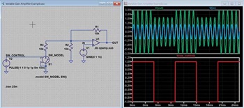
もう1つのサンプルを紹介しましょう。これは、こちらに掲載されている記事からヒントを得たものです。LTspice上では、オペアンプと電圧制御スイッチの理想的なモデルを使用した回路のシミュレーションを実行できます。サンプルの回路図(variable_gain_amplifier_example.asc)は、こちらからダウンロードすることが可能です。
図12に示した回路では、抵抗R3を介した電流のパスが繰り返しオープンと短絡の状態になります。その際、オペアンプ回路のゲインがどのように変化するのかを確認してください。

FET/スイッチ/マルチプレクサのマクロモデル
作成した回路において、理想的な電圧制御スイッチではなく、より現実的なデバイスのモデルを使用したいケースもあるでしょう。LTspiceのコンポーネントのライブラリには、様々なデバイスが用意されています。例えば、ディスクリートのトランジスタ製品、アナログ・デバイセズのスイッチICやマルチプレクサICなども含まれています。そうしたデバイスの現実的なモデルも簡単に使用することができます。
まとめ
アナログ・デバイセズは、LTspiceを使用する上で役に立つヒントやテクニックなどの情報を提供しています。詳しくは「LTspiceの技術情報とガイド」をご覧ください。
