

Overview
設計リソース
説明
The MAXREFDES77# peripheral module provides the necessary hardware to interface the MAX44285 dual-channel high-side current-sense amplifier device to any system that utilizes Pmod™-compatible expansion ports configurable for SPI communication. The IC features an input common-mode voltage range from 2.7V to 76V with 80kHz small-signal bandwidth, making it ideal for interfacing with a SAR ADC for multichannel, multiplexed data acquisition systems.
Refer to the MAX44285 IC data sheet for detailed information regarding operation of the IC and the USB2PMB1# (Munich) adapter board data sheet for detailed information regarding the Munich board and GUI.
機能と利点
- 2.7V to 76V Input Common Mode
- Low 12μV (max) Input Offset Voltage
- Low 0.1% (max) Gain Error
- Gain = 20V/V and 100V/V
- RoHS Compliant
- Proven PCB Layout
- Fully Assembled and Tested
Details Section
The MAXREFDES77# peripheral module can plug directly into a Pmod-compatible port (configured for SPI) through connector X1. For information on the SPI protocol, refer to the MAX11125 IC data sheet.
Connector X1 provides connection of the module to the Pmod host. See Table 1 for detailed description.
Connectors X3 and X4 provide connection to external power and the system loads.
Voltage Reference
The MAXREFDES77# peripheral module contains the MAX6126A30+ voltage reference to provide 3.0V reference to the ADC MAX11125.
Temperature Sensor
The MAXREFDES77# peripheral module also contains a temperature sensor, MAX6607IXK+, to measure the external temperature.
Software (GUI)
The Munich GUI is available for download and is provided to facilitate the evaluation of the MAXREFDES77#. Refer to the Munich GUI Quick Start Guide document for further details.
| Pin | Signal | Description |
|---|---|---|
| 1 | SPI_CS | Chip Select. Assert low to enable the SPI interface. |
| 2 | N.C. | No Connection |
| 3 | SPI_MOSI | MAX44285 Serial Data Input |
| 4 | Active-Low CONVST | ADC Conversion Control Input. Assert low to initiate an ADC conversion. |
| 5 | SPI_MISO | MAX44285 Serial Data Output |
| 6 | Active-Low EOC | End of Conversion Output. Data is valid after active-low EOC pulls low. |
| 7 | SPI_SCLK | MAX44285 Serial Clock Input |
| 8 | N.C. | No Connection |
| 9 | GND | Ground |
| 10 | GND | Ground |
| 11, 12 | +3.3V | +3.3V Power Supply |
The MAXREFDES77# allows measuring supply-voltage (up to 65V) and supply-current (up to 26A) for 2 different loads with independent supplies.
Procedure
- Connect supply voltage between RS+ and GND.
- Connect load resistor between RS- and GND.
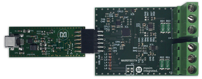
- Connect the MAXREFDES77# to the Munich via the Pmod connector.
- Connect the Munich board to a PC via a USB cable as shown in Figure 1.
- In the Munich GUI, select REFDES77 – Current Sense under the Device tab.
- Click Scan Adapter.
- Press Connect. Munich GUI will then allow you to start sampling from the MAXREFDES77# board.
- Click Sample continuously. The Munich GUI will then plot the selected Physical Values and update static levels in real time. The Y-axis on the left shows the voltage. The second Y-axis on the right depicts the Current, and the third Y-axis on the far right displays the temperature. Scaling the Y-axes can be done manually in the calibration window, so the range of interest can be plotted.
- Press the Calibrate button to perform linear calibration for accurate measurements. When in calibration mode, it is necessary to select ADC Counts in the Plot Configuration and keep Sample continuously running. See Figure 2.

Figure 1. MAXREFDES77# connected to Munich board.

Figure 2. MAXREFDES77#/Munich GUI.
- Offset calibration
- Volt per LSB calibration
- Ampere per LSB calibration
To perform offset calibration, connect both RS1- and RS2- to GND. Then observe and enter the numbers printed in Physical Values box to the appropriate Offset Textboxes (voltage and current).
To perform Volt per LSB calibration, apply a known voltage to both RS1- and RS2-. Note that the measurement range is up to 65V, but for good calibration the applied voltage should be < 75% of the allowed range. Use an accurate multimeter that has 1mV or better accuracy. See Figure 3. Divide the applied voltage level (i.e. 60V) by the number shown in Physical Value box. Then subtract the 0V Offset. The result yields the weight of 1 LSB, which should be about 0.0165V.
Volt per LSB = 60V/(ADCcounts at 60V - ADCcounts at 0V)
To perform ampere per LSB calibration, apply a known voltage to RS+ and connect a load from RS- to GND. Then, measure the current through the load with an ampmeter. There are two available gain options: 20x (MAX44285T) and 100x (MAX44285H). If the gain is 20, then the current-range is up to ~27A. If the gain is 100, then the current range is up to ~5.4A.
For accurate calibration, use load with current at ~75% of the range.
A per LSB = 20A/(ADCcounts at 20A - ADCcounts at 0A)
The Munich GUI automatically saves these calibration settings once the calibration menu is closed. Therefore, if the same hardware is used, it is not necessary to re-calibrate.

Figure 3. Calibration menu.
Lab Measurements
The MAXREFDES77# reference design was verified and tested under full input range and different output load conditions, and the results were captured by Munich GUI as shown in Figure 4.

Figure 4. MAXREFDES77# lab measurements.
Pmod is a trademark of Digilent Inc.
Documentation & Resources
-
MAXREFDES77 Design Files2021/02/18ZIP460 K
Support & Training
Search our knowledge base for answers to your technical questions. Our dedicated team of Applications Engineers are also available to answer your technical questions.